An adjustable door stopper assembly
A door device and component technology, which is applied in the direction of building fastening devices, wing fastening devices, buildings, etc., can solve the problems of inconvenient installation, high installation position accuracy requirements, and difficulty in ensuring the stability of the door body.
- Summary
- Abstract
- Description
- Claims
- Application Information
AI Technical Summary
Problems solved by technology
Method used
Image

Examples
Embodiment 1
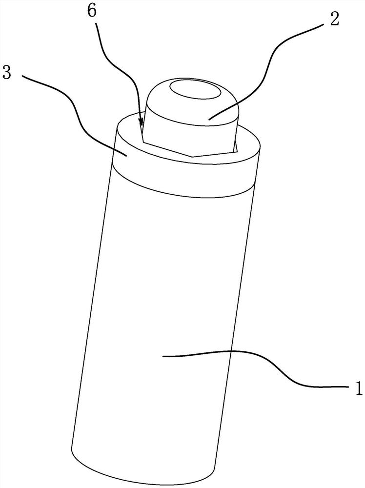
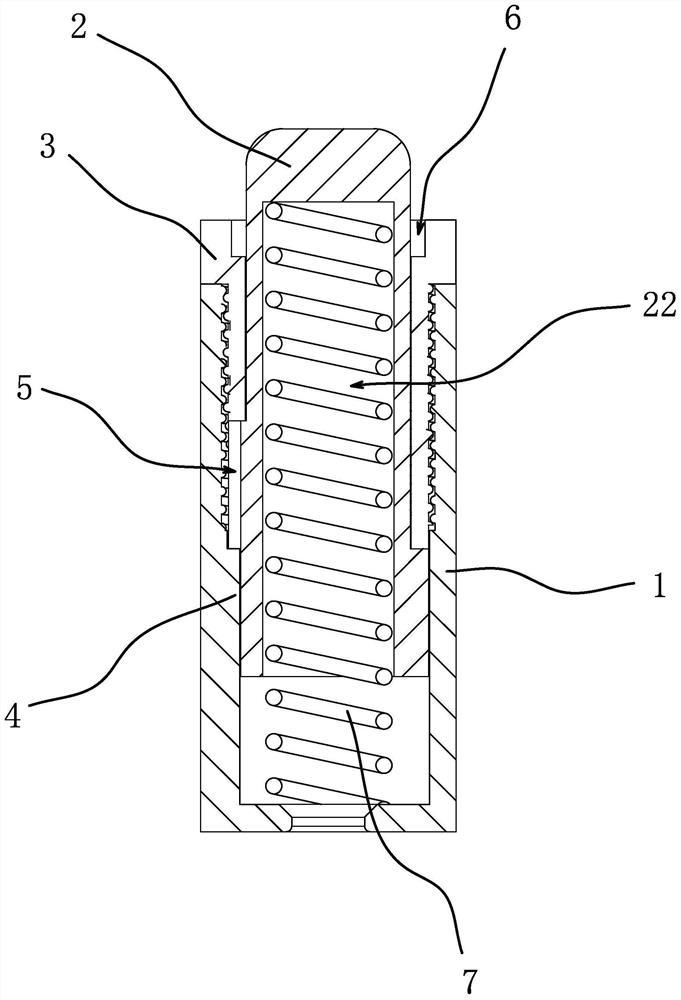
[0052] like Figure 1-6 As shown, the adjustable door stopper assembly includes a cylinder body 1 with one end open. The cylinder body 1 is provided with a limit pin 2 that can reciprocate axially along the cylinder body 1 and always has a tendency to move outwards. The outer end of the pin 2 is magnetic, and the open end of the cylinder body 1 is screwed and fitted with an adjusting block 3 that can be fed axially along the cylinder body 1 through rotation. The adjusting block 3 is cylindrical, and the outer end of the limit pin 2 It is in the shape of a round head and penetrates and extends out of the adjustment block 3. The limit pin 2 has a limit portion 21. The limit portion 21 and the inner end of the adjustment block 3 are axially limited and abutted along the circumferential direction to form a limit. , the limit pin 2 cooperates with the cylinder body 1 along the circumferential direction, and when the limit pin 2 is controlled to move inward, the adjustment block 3 c...
Embodiment 2
[0055] like Figure 7-11 As shown, this embodiment is basically the same as the first embodiment, the difference is that: the inner side wall of the cylinder body 1 has two vertically arranged notch grooves 5, and the outer peripheral surface of the limit pin 2 has two along the limit pin 2 The axially arranged rib 4, the notch groove 5 cooperates with the rib 4 and makes the limit pin 2 form a limit along the circumferential direction, when the limit pin 2 is controlled to move inward, the rib 4 and the notch groove 5 can be separated and separated Release the circumferential limit. A vertically arranged notch groove 5 is provided on the inner side wall of the cylinder body 1, and a convex rib 4 is arranged on the outer peripheral surface of the limit pin 2 along the axial direction of the limit pin 2. The notch groove 5 cooperates with the convex rib 4 to make the limit The position pin 2 forms a circumferential limit, so that when the limit pin 2 is controlled to move inwa...
Embodiment 3
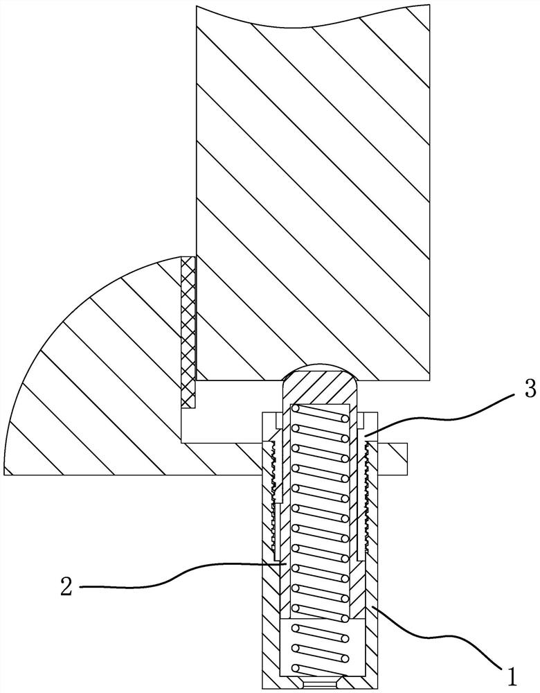
[0057] like Figure 12 As shown, this embodiment is basically the same as the first embodiment, the difference is that: the limit pin 2 includes a limit cylinder 23 and a ball 24 that is located in the limit cylinder 23 and always has a tendency to move outward, and the ball 24 is a metal iron The ball 24 and the inner edge of the outer end of the limiting cylinder 23 axially limit and abut, and the ball 24 partially protrudes from the outer end of the limiting cylinder 23 . By setting the limit pin 2 to include a limit cylinder 23 and a ball 24, the ball 24 partially protrudes from the outer end of the limit cylinder 23, and the ball 24 is continuously subjected to an outward force so that it can cooperate with the positioning groove at the bottom of the door body to limit the limit When the door body moves relative to the limit pin 2, the balls 24 can roll along the bottom surface of the door body, thereby reducing the movement resistance, making the movement smoother and re...
PUM
 Abstract
Description
Claims
Application Information
 - R&D
- Intellectual Property
- Life Sciences
- Materials
- Tech Scout
- Unparalleled Data Quality
- Higher Quality Content
- 60% Fewer Hallucinations
Browse by: Latest US Patents, China's latest patents, Technical Efficacy Thesaurus, Application Domain, Technology Topic, Popular Technical Reports.
© 2025 PatSnap. All rights reserved.Legal|Privacy policy|Modern Slavery Act Transparency Statement|Sitemap|About US| Contact US: help@patsnap.com