Rotational flow blade type mixer

A swirl blade and mixer technology, which is used in machines/engines, mufflers, exhaust gas treatment, etc., can solve the problems of insufficient airflow velocity, insufficient mixing path, insufficient urea crushing, and affecting the effect of urea crushing and decomposition, so as to speed up the airflow. Speed, increase mixing path, urea crushing and decomposition effect enhanced effect

Pending Publication Date: 2021-06-11
KAILONG HIGH TECH
View PDF0 Cites 1 Cited by
  • Summary
  • Abstract
  • Description
  • Claims
  • Application Information

AI Technical Summary

Problems solved by technology

However, due to factors such as insufficient air velocity and too short mixing path, the effect of urea crushing and decomposition will be affected, resulting in insufficient urea crushing, and urea crystals are easily formed on the mixer and the downstream pipe wall of the mixer.

Method used


Image

  • Rotational flow blade type mixer
  • Rotational flow blade type mixer
  • Rotational flow blade type mixer

Examples


Embodiment Construction

[0016] The technical solutions of the present invention will be further described below in conjunction with the accompanying drawings and through specific implementation methods.

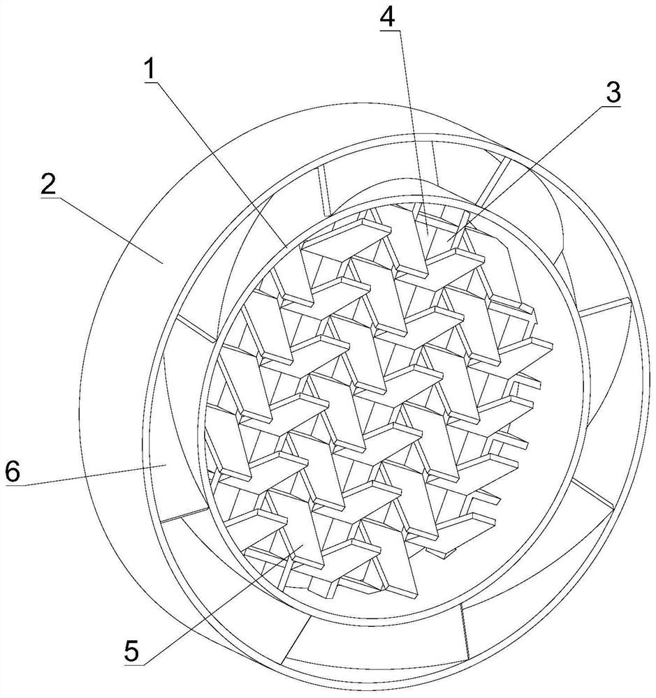
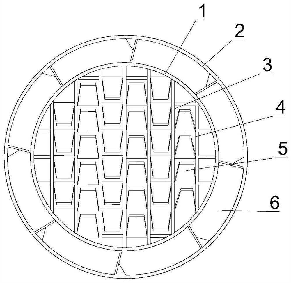
[0017] see Figures 1 to 3 As shown, this embodiment provides a swirling vane mixer, which includes an inner cylinder 1 and an outer cylinder 2 coaxially arranged, and a grid frame 3 is arranged in the inner cylinder 1, and the grid frame 3 will The chamber of the inner cylinder body 1 is divided into flow channels 4 one by one.

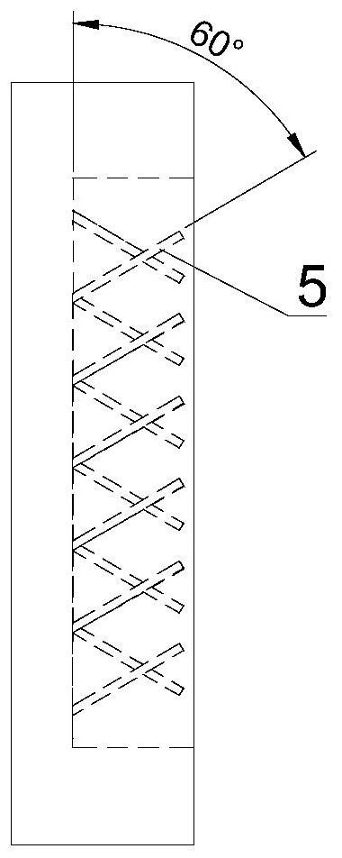
[0018] The frame of each flow channel 4 extends upwards with inclined blades 5, and the inclined blades 5 block and break the urea solution in the flow channel 4 therein. In order to facilitate forming and reduce the difficulty of forming complex shaped blades, each inclined blade 5 is uniformly arranged on the frame edge of the horizontal row or the vertical frame edge, and the orientation of the inclined blades 5 in adjacent rows or columns is opposite. This shape is en...


PUM


Abstract

The invention discloses a rotational flow blade type mixer. The mixer comprises an inner cylinder body and an outer cylinder body which are coaxially arranged; a grid frame is arranged in the inner cylinder body; a cavity of the inner cylinder body is divided into flow channels by the grid frame; the frame edge of each flow channel extends upwards to form an inclined blade; each inclined blade blocks urea liquid in the corresponding flow channel where the inclined blade is located, and the urea liquid in the corresponding flow channel where the inclined blade is located is crushed; multiple rotational flow blades are uniformly distributed between the inner cylinder body and the outer cylinder body, so that air flow passing through a gap between the two cylinder bodies forms rotational flow. The rotational flow blade type mixer is provided with a large number of inclined blades which are arranged in order, so that the urea crushing and decomposing effect is greatly enhanced; meanwhile, the rotational flow blades are additionally arranged to enable the air flow to be disordered in a spiral mode, the air flow speed is increased, the urea mixing path is increased, the liquid urea is prevented from being accumulated in the mixer and the downflow pipe wall of the mixer, urea crystallization is effectively eliminated, and the problem of low carrier conversion efficiency is solved.

Description

technical field [0001] The invention relates to the technical field of diesel engine tail gas treatment, in particular to a swirling vane mixer. Background technique [0002] In order to solve the problem of high pollutant content in diesel engine exhaust, selective catalytic reduction technology (SCR) is widely used for exhaust gas treatment of diesel engine emissions. In the SCR system, the gas density has a great influence on NO X The reduction and decomposition of urea have a great influence, when the gas NO X with NH 3 The higher the mixing uniformity, the more fully the reaction, the NO X The higher the conversion efficiency. Therefore, the exhaust gas and NH in the SCR system are increased 3 The uniformity of mixing is an important means to improve the performance of SCR system. Such as Figure 4 As shown, an injector 2' is installed on the exhaust pipe 1', and a mixer 3' is installed in the pipe. The urea column injected by the injector 2' hits the mixer 3', and...

Claims


Application Information

Patent Timeline
Patent Type & Authority Applications(China)
IPC IPC(8): F01N3/28F01N3/20
CPCF01N3/2066F01N3/2892F01N2610/02
Inventor 朱正富臧志成刘德文杨新郁子安张仕玉
Owner KAILONG HIGH TECH
Why Eureka
Try Eureka