Rotational flow disturbance device and heat exchange pipe structure

A technology of heat exchange tubes and swirling flow, applied in the field of heat exchange tubes, can solve the problems of large flow pressure drop of heat exchange tubes, achieve the effects of solving excessive flow pressure drop, compact and reliable structure, and improving effective utilization

Active Publication Date: 2021-06-11
GREE ELECTRIC APPLIANCES WUHAN +1
View PDF7 Cites 1 Cited by
  • Summary
  • Abstract
  • Description
  • Claims
  • Application Information

AI Technical Summary

Problems solved by technology

[0005] The main purpose of the present invention is to provide a swirl disturbance device and a heat exchange tube structure to solve the problem of excessive flow pressure drop in a heat exchange tube with a swirler in the prior art

Method used


Image

  • Rotational flow disturbance device and heat exchange pipe structure
  • Rotational flow disturbance device and heat exchange pipe structure
  • Rotational flow disturbance device and heat exchange pipe structure

Examples


Embodiment Construction

[0031] It should be noted that, in the case of no conflict, the embodiments in the present application and the features in the embodiments can be combined with each other. The present invention will be described in detail below with reference to the accompanying drawings and examples.

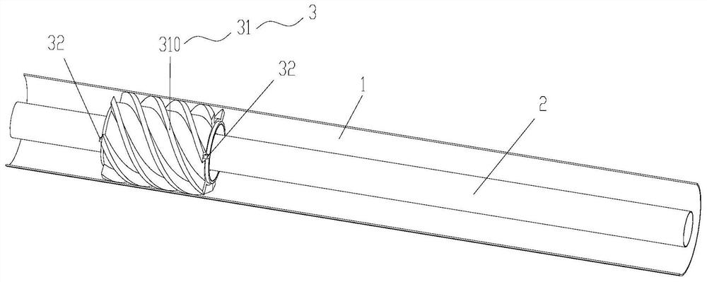
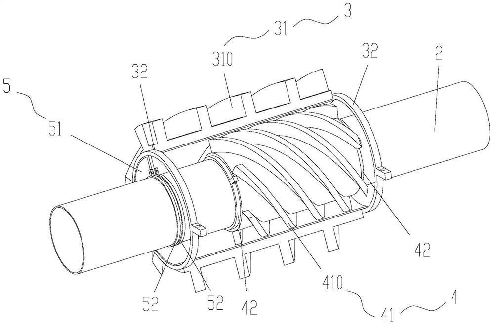
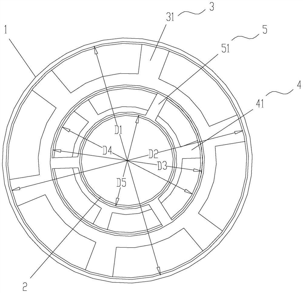
[0032] Such as Figure 1 to Figure 8As shown, the present invention provides a swirl disturbance device for installation in a heat exchange tube structure, the heat exchange tube structure includes a first tube 1 and a second tube 2 pierced in the first tube 1; the first The pipe 1 and the second pipe 2 are arranged at intervals to form an annular flow path for the flow of the first fluid; the second pipe 2 is used for the flow of the second fluid; the temperature of the first fluid is different from the temperature of the second fluid The same; the swirl disturbance device includes: a first swirl assembly 3 and a second swirl assembly 4, the position between the first swirl assembly 3 and the...


PUM


Abstract

The invention provides a rotational flow disturbance device and a heat exchange pipe structure. The rotational flow disturbance device is used for being installed in the heat exchange pipe structure, and the heat exchange pipe structure comprises a first pipe and a second pipe arranged in the first pipe in a penetrating mode. An annular flow path for a first fluid to flow is formed between the first pipe and the second pipe. The second pipe allows a second fluid to flow. The first fluid and the second fluid are different in temperature. The rotational flow disturbance device comprises a first rotational flow assembly and a second rotational flow assembly which are relatively fixed. The first rotational flow assembly is arranged in the first pipe in a penetrating mode and sleeves the second rotational flow assembly, and the second rotational flow assembly sleeves the second pipe and is detachably connected with the second pipe. A first external thread is arranged outside the first rotational flow assembly, a second external thread is arranged outside the second rotational flow assembly, the annular flow path is divided into a first spiral flow channel located between the first external thread and the first rotational flow assembly and a second spiral flow channel located between the second external thread and the second rotational flow assembly. The problem that in the prior art, the flowing pressure drop in a heat exchange pipe with a swirler is too large is solved.

Description

technical field [0001] The invention relates to the field of heat exchange tubes, in particular to a swirl disturbance device and a heat exchange tube structure. Background technique [0002] The heat exchange tube is the core component of the heat exchange equipment, and the actual heat exchange performance of the heat exchange equipment is always affected by the material properties and shape structure of the heat exchange tube. In order to enhance the heat transfer effect in the tube, it is more common to use the flow pattern in the tube disturbed by the swirl flow. After the fluid flows through the cyclone, a strong vortex flow is formed to reduce the thickness of the boundary layer and promote heat and mass transfer in the tube. It can also have a strong scouring effect on the tube wall, thereby reducing the scale on the inner wall of the tube. Formed to reduce the hindrance of heat transfer. [0003] In the form of swirling disturbance of the heat exchange tube in the...

Claims


Application Information

Patent Timeline
Patent Type & Authority Applications(China)
IPC IPC(8): F28D7/10F28F13/12
CPCF28D7/10F28F13/125
Inventor 冯家杰李丽霞宋美琪
Owner GREE ELECTRIC APPLIANCES WUHAN
Why Eureka
Try Eureka