Shock absorber assembly load signal acquisition device

A load signal and acquisition device technology, applied in the field of vehicle shock absorbers, can solve problems affecting the accuracy of strain gauge signals, reduce the quality of collected signals, and reduce design accuracy, so as to improve development efficiency, signal quality, and accuracy Effect

Pending Publication Date: 2021-06-11
MAGNA STEYR AUTOMOTIVE TECHNOLOGY (SHANGHAI) LTD
View PDF0 Cites 0 Cited by
  • Summary
  • Abstract
  • Description
  • Claims
  • Application Information

AI Technical Summary

Problems solved by technology

Based on this design, in order to improve the accuracy of the simulation results in the virtual design stage, the engineering team will use the form of separately attaching strain gauges to the shock absorber piston rod and spring to obtain the spring and shock absorber in the road spectrum collection of the test vehicle The load signal of the piston rod supports virtual development to improve the quality and accuracy of the virtual design. However, when the vehicle is running, especially on bad roads, the temperature of the shock absorber will increase, and the temperature of the shock absorber piston rod will also increase. The increase will affect the signal accuracy of the strain gauge and reduce the quality of the collected signal, which will lead to a decrease in design accuracy, resulting in high cost engineering change costs in the later stage, and at the same time causing waste of development time and affecting project progress; on the other hand, The signal collected after the spring patch is affected by key parameters such as the stiffness of the spring itself and the design height, which will cause deviations from the design parameters

Method used


Image

  • Shock absorber assembly load signal acquisition device
  • Shock absorber assembly load signal acquisition device
  • Shock absorber assembly load signal acquisition device

Examples


Embodiment Construction

[0016] Below in conjunction with accompanying drawing, the present invention will be further described as follows:

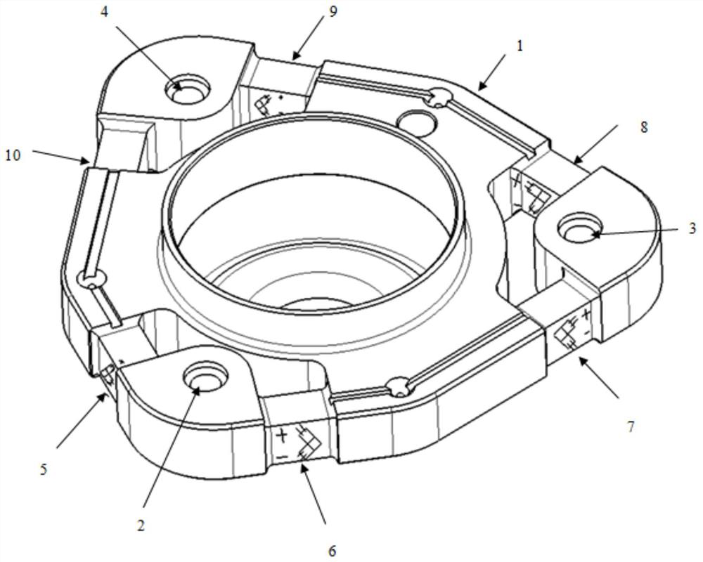
[0017]The invention provides a shock absorber assembly load signal acquisition device, which comprises a shock absorber assembly body 1, and the shock absorber assembly body 1 is evenly distributed along the circumferential direction with mounting holes 1, 2, and 3. Three 4, the left and right sides of installation hole one 2 are respectively provided with strain gauge installation groove one 5, strain gauge installation groove two 6, and the left and right sides of installation hole two 3 are respectively provided with strain gauge installation groove three 7, strain gauge installation groove four 8 , the left and right sides of installation hole three 4 are respectively provided with strain gauge installation groove five 9, strain gauge installation groove six 10, strain gauge installation groove one 5, strain gauge installation groove two 6, strain gauge insta...


PUM


Abstract

The invention relates to a shock absorber assembly load signal acquisition device which comprises a shock absorber assembly body, a first mounting hole, a second mounting hole and a third mounting hole are distributed in the shock absorber assembly body, and a first strain gauge mounting groove and a second strain gauge mounting groove are formed in the left side and the right side of the first mounting hole respectively. A third strain gauge mounting groove and a fourth strain gauge mounting groove are formed in the left side and the right side of the second mounting hole respectively, a fifth strain gauge mounting groove and a sixth strain gauge mounting groove are formed in the left side and the right side of the third mounting hole respectively, each strain gauge mounting groove is provided with a set of strain gauge sensors, the positions of each set of strain gauge sensors are divided into the outer side and the inner side, and each side is divided into the positive electrode and the negative electrode. Positive and negative electrodes of the six groups of strain gauge sensors are connected in series to form a signal collection unit with a signal positive electrode, a signal negative electrode, a power supply positive electrode and a power supply negative electrode; objective and accurate load signals can be obtained, the accuracy of virtual design is improved, the number of times of engineering change is reduced, the development time and cost are saved, and the vehicle development efficiency is improved.

Description

[technical field] [0001] The invention relates to the technical field of vehicle shock absorbers, in particular to a shock absorber assembly load signal acquisition device. [Background technique] [0002] Shock absorbers are a key part of a vehicle to enhance comfort and control handling. In passenger cars and trucks, it is necessary to design and arrange at least two shock absorbers on each axle to ensure the comfortable operation of the vehicle. So affected. At present, the front suspension shock absorber assembly of a passenger car mainly uses a sliding column assembly in which the shock absorber 25, the spring 24, the buffer block 23, the bearing 22, and the upper support assembly 21 are assembled into one, as attached figure 1 shown. Based on this design, in order to improve the accuracy of the simulation results in the virtual design stage, the engineering team will use the form of separately attaching strain gauges to the shock absorber piston rod and spring to obt...

Claims


Application Information

Patent Timeline
Patent Type & Authority Applications(China)
IPC IPC(8): G01M13/02G01M17/007
CPCG01M13/02G01M17/007
Inventor 田德明杨辉陈良周亮杨越
Owner MAGNA STEYR AUTOMOTIVE TECHNOLOGY (SHANGHAI) LTD
Why Eureka
Try Eureka