Cooling pipe assembly with static electricity releasing function, cooling device and plasma processing equipment

A technology for cooling devices and cooling pipes, applied in discharge tubes, electrical components, circuits, etc., can solve the problems of hose 30 damage, interference with substrate adsorption, liquid leakage, etc., to improve safety, prevent arcs, and reduce failures The effect of the probability

Pending Publication Date: 2021-06-11
ADVANCED MICRO FAB EQUIP INC CHINA
View PDF13 Cites 0 Cited by
  • Summary
  • Abstract
  • Description
  • Claims
  • Application Information

AI Technical Summary

Problems solved by technology

[0003] In the prior art, the insulating rubber hose 30 is connected to the cooling channel in the substrate 10 to provide and recover cooling liquid. When the liquid flows through and scrapes the inner wall of the hose 30, the inner wall is easy to accumulate charges, and these charges are related to radio frequency (RF) There will be a discharge phenomenon between the rods, resulting in damage to the hose 30 and leakage
At the same time, charges will also accumulate on the inner wall of the cooling channel, and these charges will induce charges of opposite polarity on the electrostatic chuck, thereby interfering with the adsorption force of the electrostatic chuck to the substrate and affecting the safety of wafer movement

Method used


Image

  • Cooling pipe assembly with static electricity releasing function, cooling device and plasma processing equipment
  • Cooling pipe assembly with static electricity releasing function, cooling device and plasma processing equipment
  • Cooling pipe assembly with static electricity releasing function, cooling device and plasma processing equipment

Examples


no. 1 example 〉

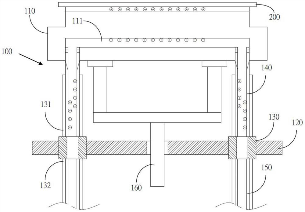
[0025] see figure 2 , which is a schematic diagram of the first embodiment of the cooling device with static discharge function of the present invention. As shown in the figure, the first embodiment of the present invention provides a cooling device 100 with the function of discharging static electricity, which includes a substrate 110, a radio frequency shielding plate 120, a cooling pipe connector 130, a high resistance cooling pipe 140 and a metal cooling pipe 150.

[0026] Furthermore, a cooling channel 111 is disposed in the substrate 110 , and an electrostatic chuck (ESC) 200 is connected above the substrate 110 . The radio frequency shielding plate 120 is disposed under the substrate 110 . The cooling pipe connector 130 is disposed in the radio frequency shielding plate 120 , and has a first end 131 and a second end 132 of the cooling pipe connector 130 on the upper surface and the lower surface of the radio frequency shielding plate 120 respectively. One end of the...

no. 2 example

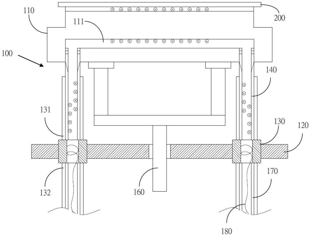
[0037] see image 3 , which is a schematic diagram of the second embodiment of the cooling device with static discharge function of the present invention. As shown in the figure, the second embodiment of the present invention is to provide in order to achieve the above purpose, the second technical solution of the present invention is to provide a cooling device 100 with the function of discharging static electricity, the substrate 110, the radio frequency shielding plate 120, and the cooling pipe are connected Device 130, high resistance cooling pipe 140 and non-metallic cooling pipe 160

[0038] Furthermore, a cooling channel 111 is disposed in the substrate 110 , and the electrostatic chuck 200 is connected above the substrate 110 . The radio frequency shielding plate 120 is disposed under the substrate 110 . The cooling pipe connector 130 is disposed in the radio frequency shielding plate 120 , and has a first end 131 and a second end 132 of the cooling pipe connector 130 ...

no. 3 example 〉

[0049] see Figure 4 , which is a schematic diagram of the third embodiment of the cooling device with static discharge function of the present invention. As shown in the figure, the third embodiment of the present invention is to provide in order to achieve the above purpose, the third technical solution of the present invention is to provide a cooling device 100 with the function of discharging static electricity, which includes a substrate 110, a radio frequency shielding plate 120, a cooling The tube connector 130 , the high-resistance cooling tube 140 and the cooling tube 190 . The substrate 110 is provided with a cooling channel 111 , and the upper part of the substrate 110 is connected to the electrostatic chuck 200 . The radio frequency shielding plate 120 is disposed under the substrate 110 . The cooling pipe connector 130 is disposed in the radio frequency shielding plate 120 , and has a first end 131 and a second end 132 of the cooling pipe connector 130 on the upp...


PUM


Abstract

The invention relates to a cooling device with a static electricity releasing function and a cooling pipe assembly. The cooling device comprises a substrate, a radio frequency shielding plate, a cooling pipe connector, a high-resistance cooling pipe and a metal cooling pipe. A cooling channel is arranged in the substrate. The radio frequency shielding plate is arranged below the substrate. The cooling pipe connector is arranged in the radio frequency shielding plate, and a first end and a second end of the cooling pipe connector are arranged on the upper surface and the lower surface of the radio frequency shielding plate respectively. One end of the high-resistance cooling pipe is connected with the cooling channel in the substrate, and the other end of the high-resistance cooling pipe is connected with the first end of the cooling pipe connector. One end of the metal cooling pipe is connected with the second end of the cooling pipe connector, and the other end of the metal cooling pipe is grounded. The arc phenomenon caused by static electricity charges is avoided through the high-resistance characteristic of the high-resistance cooling pipe, and on the other hand, the static electricity charges are conducted away through grounding of the cooling pipe, so that the probability of failure of the static electricity chuck is reduced, and the safety of wafer movement is improved.

Description

technical field [0001] The invention relates to devices in the field of semiconductors, in particular to a cooling pipe assembly with the function of releasing static electricity, a cooling device and plasma processing equipment. Background technique [0002] see figure 1 , which is a schematic diagram of a cooling device for a plasma processing apparatus. As shown in the figure, on the substrate 10 is an electrostatic chuck (ESC) 20 , and the electrostatic chuck 20 and the substrate 10 are collectively referred to as an electrostatic chuck device. The substrate is held on the electrostatic chuck. When the plasma etches the substrate, a large amount of heat will be generated on the substrate, therefore, the substrate needs to be cooled. Usually, a cooling channel is provided in the substrate 10 , and the purpose of cooling the electrostatic chuck 20 and thus the substrate is achieved by circulating water or heat transfer fluid in the cooling channel. [0003] In the prio...

Claims


Application Information

Patent Timeline
IPC IPC(8): H01J37/32H01L21/67
CPCH01J37/32431H01J37/32724H01J37/32651H01L21/67069H01J2237/334
Inventor 龚岳俊黄允文
Owner ADVANCED MICRO FAB EQUIP INC CHINA
Why Eureka
Try Eureka