Exhaust gas discharge nozzle

A nozzle and exhaust flow path technology, applied in the field of exhaust outlet nozzles, can solve problems such as inability to monitor pressure

Active Publication Date: 2020-10-30
KAWASAKI HEAVY IND LTD
View PDF11 Cites 0 Cited by
  • Summary
  • Abstract
  • Description
  • Claims
  • Application Information

AI Technical Summary

Problems solved by technology

However, it is possible that pressure monitoring is not possible
Furthermore, this disadvantage is a common problem in combustion equipment that generates corrosive high-temperature exhaust gas, and is a common problem in nozzles that lead out exhaust gas regardless of the application.
In addition, since some residual stress due to processing is generated in the fixing part, this defect is also a common problem in fixing methods other than welding.

Method used


Image

  • Exhaust gas discharge nozzle
  • Exhaust gas discharge nozzle
  • Exhaust gas discharge nozzle

Examples


Embodiment approach 1

[0037]

[0038] First, the exhaust flow path provided with the exhaust outlet nozzle according to Embodiment 1 will be described. The exhaust flow path is not particularly limited as long as it is a flow path through which high-temperature exhaust gas that generates corrosive liquid flows when the temperature is not higher than the acid dew point. As such an exhaust gas flow path, an exhaust gas flow path of waste incineration facilities, biomass fuel combustion facilities, or by-products of chemical plants is exemplified. Hereinafter, the exhaust gas outlet nozzle will be described by taking the exhaust flow path of a waste incinerator as an example. The use of the exhaust gas extracted by the exhaust gas extraction nozzle is not particularly limited.

[0039]

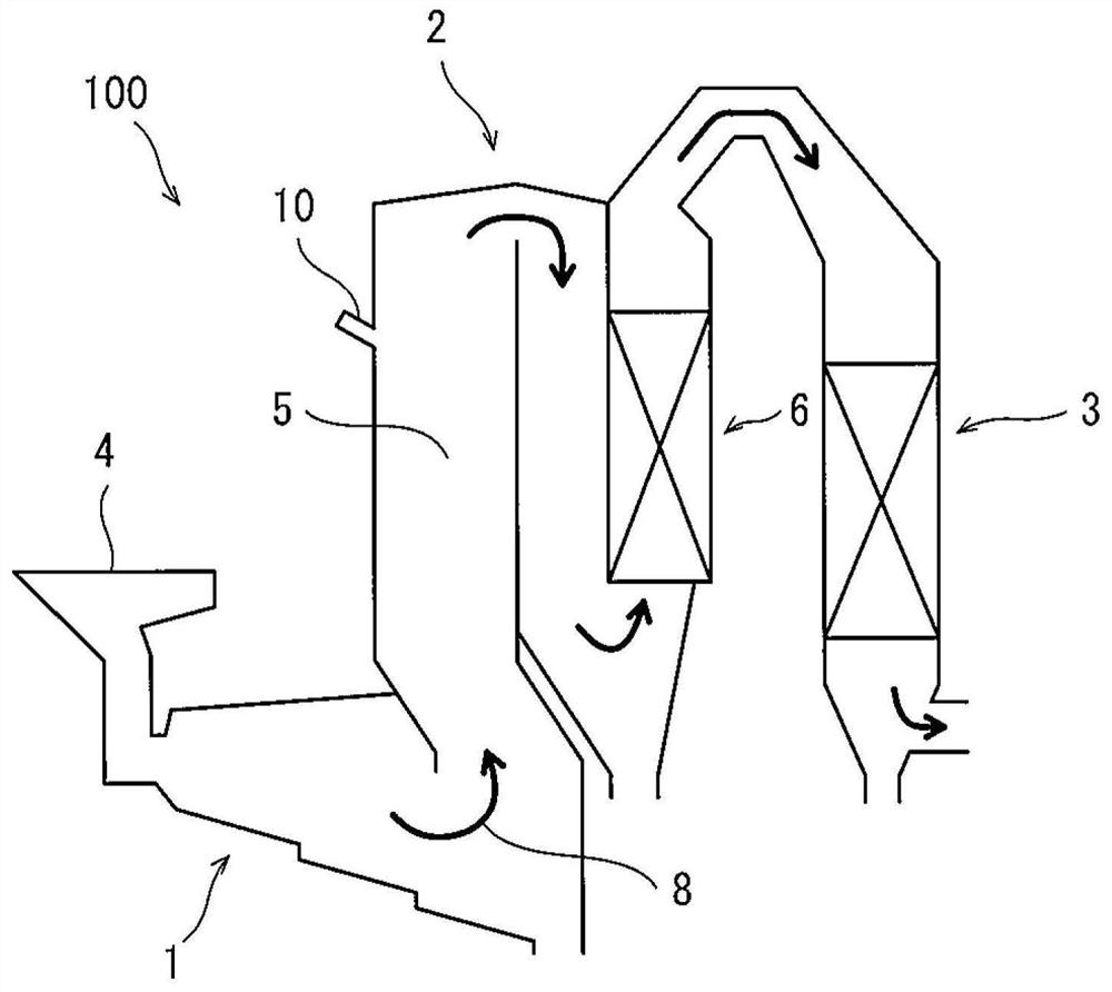
[0040] figure 1 It is a schematic diagram showing the outline of a waste incineration facility provided with the exhaust gas outlet nozzle according to the first embodiment.

[0041] refer to figure 1 , the ...

Embodiment approach 2

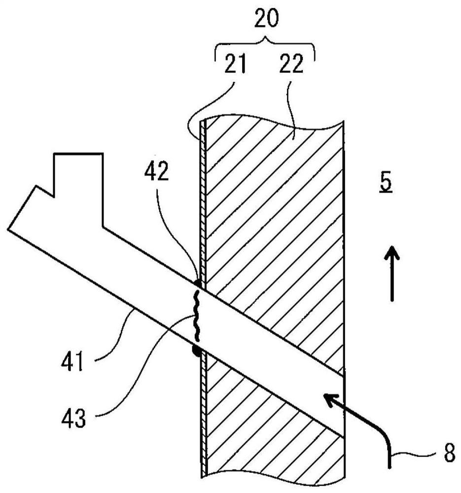
[0059] Figure 4 It is a cross-sectional view showing the configuration of the exhaust gas outlet nozzle according to the second embodiment.

[0060] refer to Figure 4 , in the exhaust outlet nozzle 10 according to Embodiment 2, the inner cylinder 12 is divided into a first portion 12A including the non-corrosion portion 15 and a second portion 12B which is a remaining portion after removing the first portion 12A from the inner cylinder 12 . The base end (lower end) of the second part 12B is in contact with the front end (upper end) of the first part 12A. The portion of the second portion 12B protruding from the outer cylinder 11 is detachably fixed to, for example, the casing 21 of the wall 20 by an appropriate fixing means that does not generate tensile stress. Other configurations are the same as those of the exhaust outlet nozzle 10 according to the first embodiment.

[0061] According to such Embodiment 2, when the thickness of the 2nd part 12B is thinned by the flowi...


PUM


Abstract

Provided is an exhaust gas discharge nozzle capable of preventing the occurrence of stress corrosion cracks in a fixed part and in the vicinity thereof. The exhaust gas discharge nozzle (10) is used for discharging exhaust gas (8) from the exhaust gas flow path (5). A high-temperature exhaust gas (8) that generates a corrosive liquid when the temperature is equal to or lower than an acid dew pointflows through an exhaust gas flow path (5), the exhaust gas discharge nozzle (10) is provided with: an outer cylinder (11) that is inserted through a through-hole (20a) in a wall (20) of the exhaustgas flow path (5) and is affixed to the wall (20); an inner cylinder (12) inserted into the outer cylinder (11) so as to have a gap from the outer cylinder (11); and a sealing structure (13) for sealing the gap. Furthermore, a non-corrosive portion (15) of the inner cylinder (12), which is a portion of the inner cylinder (12) where the temperature of the discharged exhaust gas (8) is higher than the boiling point of the corrosive liquid, is fixed to the outer cylinder (11).

Description

technical field [0001] The invention relates to exhaust gas discharge nozzles. Background technique [0002] Various nozzles are installed in the exhaust flow path of the waste incinerator. For example, in the waste incineration facility described in Patent Document 1, an injection nozzle for injecting chemical into the exhaust flow path is provided. On the other hand, the exhaust gases of known waste incineration plants are corrosive. Therefore, in this waste incineration facility, the blowing nozzle is covered with a protective pipe, thereby avoiding corrosion of the surface of the blowing nozzle. [0003] Patent Document 1: Japanese Patent Application Publication No. 2003-080116 [0004] In the exhaust flow path of a waste incinerator, for example, in order to monitor the pressure of the exhaust gas, a nozzle for leading out gas for pressure measurement from the exhaust flow path may be provided. In this case, stress corrosion cracks may occur in the nozzle. In addit...

Claims


Application Information

Patent Timeline
Patent Type & Authority Applications(China)
IPC IPC(8): F23G7/00F23G5/44F23J13/00
CPCF23G7/00F23G5/44F23J13/00
Inventor 竹本启辉原田修
Owner KAWASAKI HEAVY IND LTD
Why Eureka
Try Eureka