
Punching platform of numerical control punching machine

A stamping table and stamping machine technology, applied in the direction of feeding device, positioning device, storage device, etc., can solve the problems of inconvenient workpiece storage, poor operation flexibility, affecting the efficiency and quality of steel strip punching, and improve efficiency and its quality effect

Active Publication Date: 2021-06-15
唐山锦尚金属制品有限公司
View PDF8 Cites 2 Cited by
  • Summary
  • Abstract
  • Description
  • Claims
  • Application Information

AI Technical Summary

Problems solved by technology

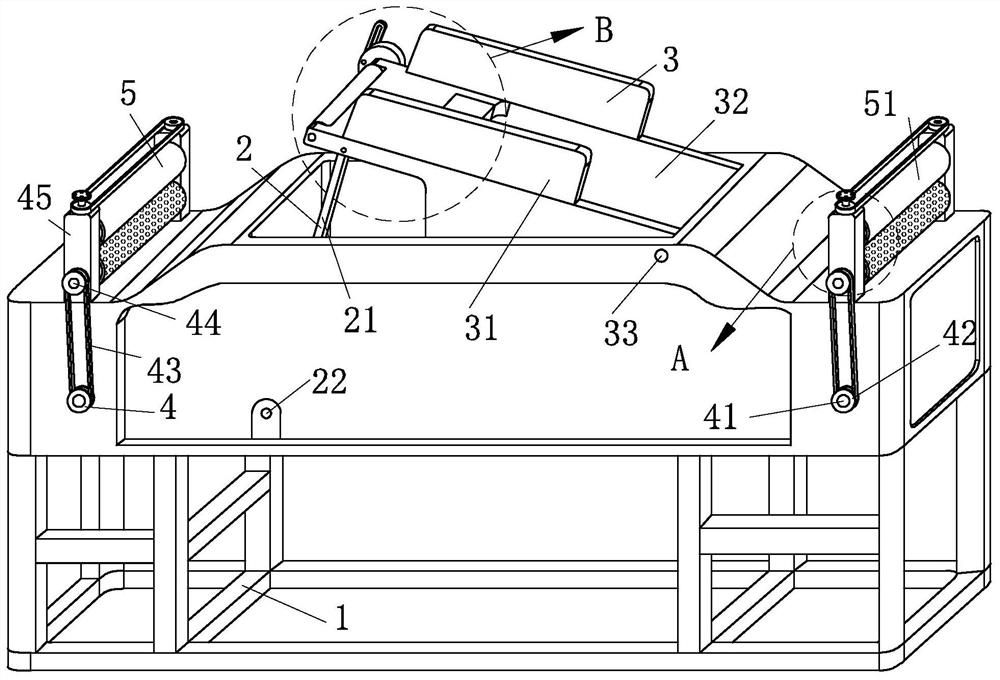
[0003]However, when the traditional CNC punching machine punches the steel strip, the steel strip is mostly placed horizontally and punched vertically by the punching machine. After the completion, it is necessary to use a push component to separate the punched component from the stamping die, which has poor operational flexibility and is not convenient for storing the blanked workpiece. At the same time, due to the smooth surface of the steel belt, it is not convenient to use the guide wheel to guide the steel belt. Then it affects the efficiency and quality of the blanking of the steel strip

Method used


Image

  • Punching platform of numerical control punching machine
  • Punching platform of numerical control punching machine
  • Punching platform of numerical control punching machine

Examples


Embodiment Construction

[0025] In order to make the technical means, creative features, goals and effects achieved by the present invention easy to understand, the present invention will be further described below in conjunction with specific embodiments.

[0026] It should be noted that the terms "first" and "second" in the description and claims of the present application and the above drawings are used to distinguish similar objects, but not necessarily used to describe a specific sequence or sequence. It should be understood that the data so used may be interchanged under appropriate circumstances for the embodiments of the application described herein. Furthermore, the terms "comprising" and "having", as well as any variations thereof, are intended to cover a non-exclusive inclusion, for example, a process, method, system, product or device comprising a sequence of steps or elements is not necessarily limited to the expressly listed instead, may include other steps or elements not explicitly lis...


PUM


Abstract

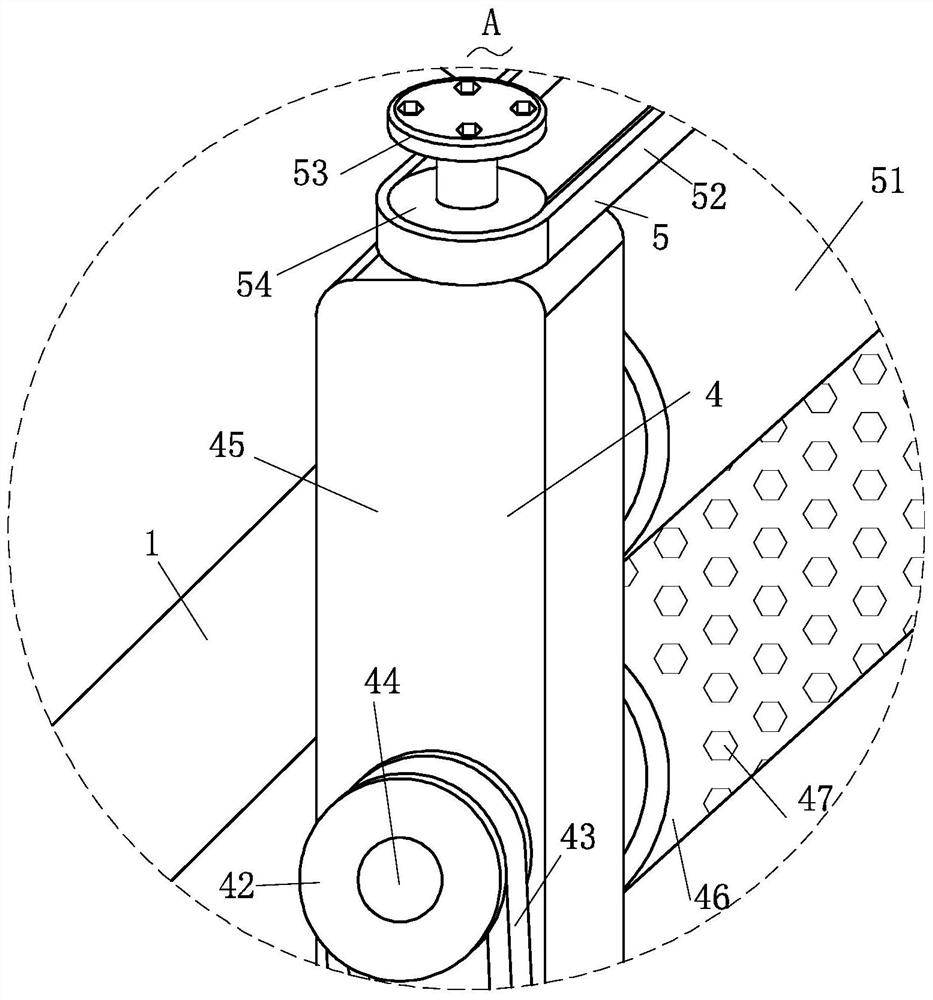
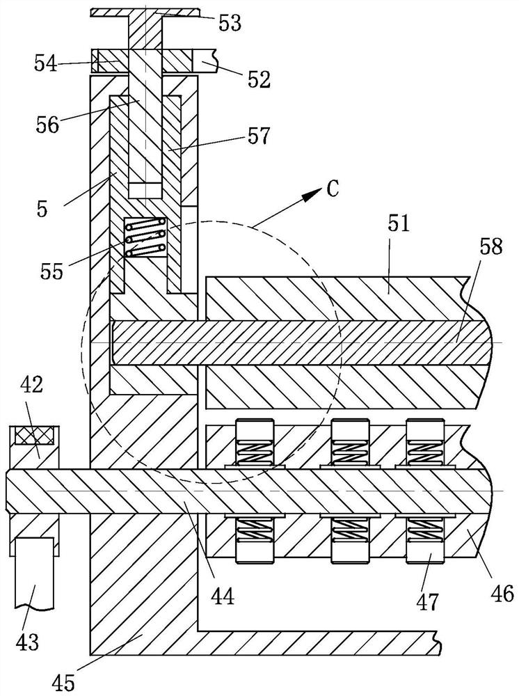
The invention relates to the field of punching platforms, and particularly discloses a punching platform of a numerical control punching machine. The punching platform comprises a punching platform body, a driving structure, a material guiding structure, a winding structure, a guiding structure, an anti-blocking structure and a discharging hopper; and the other end of the material guiding structure is connected to the driving structure used for adjusting the angle of the material guiding structure on the punching platform body. Further, the angle of the material guiding structure is conveniently adjusted through the driving structure, so that the material guiding structure is obliquely arranged, a punched workpiece is conveniently taken away from a punch die in the moving process of a steel belt, the workpiece falls into the discharging hopper from the material guiding structure under the action of gravity and then is discharged from the discharging hopper, therefore, secondary pushing and cleaning of the punched workpiece are avoided, and the punching efficiency and quality are greatly improved; and due to the arrangement of the anti-blocking structure, the steel belt drives the anti-blocking structure to move in the material guiding structure in the moving process, the punched workpiece is effectively prevented from being blocked in the material guiding structure, and the punched workpiece is more convenient and faster to clean.

Description

technical field [0001] The invention relates to a punching platform, in particular to a punching platform of a numerically controlled punching machine, which belongs to the field of punching platforms. Background technique [0002] CNC punching machine is the abbreviation of digital control punching machine. It is an automatic machine tool equipped with a program control system. The control system can logically process programs with control codes or other symbolic instructions and decode them, so that the punching machine can move. And processing parts, can be used for processing various metal sheet parts, can automatically complete a variety of complex pass and shallow stretch forming processing at one time, (automatically process holes of different sizes and hole distances of different shapes according to requirements, and small dies can also be used Punching large round holes, square holes, waist-shaped holes and various shapes of curved contours by nibbling), can also be...

Claims


Application Information

Patent Timeline
Patent Type & Authority Applications(China)
IPC IPC(8): B21D28/02B21D28/04B21D43/02B21D45/04B21C47/34B21C47/04B21C47/18
CPCB21D28/02B21D28/04B21D43/02B21D45/04B21C47/34B21C47/04B21C47/18
Inventor 张嘉乐刘赫海
Owner 唐山锦尚金属制品有限公司
Learn More