Rotor spot welding device

A spot welding device and rotor technology, applied in welding equipment, resistance welding equipment, metal processing equipment, etc., can solve the problems of complicated rotor operation steps, and achieve the effect of complete automation of the welding process and realization of the welding process

Active Publication Date: 2021-06-15
重庆宝优机电有限公司
View PDF6 Cites 0 Cited by
  • Summary
  • Abstract
  • Description
  • Claims
  • Application Information

AI Technical Summary

Problems solved by technology

[0004] The purpose of the present invention is to provide a rotor spot welding device to solve the technical problem of complex operation steps of the rotor in the spot welding process

Method used


Image

  • Rotor spot welding device
  • Rotor spot welding device

Examples


Embodiment Construction

[0028] The following is further described in detail through specific implementation methods:

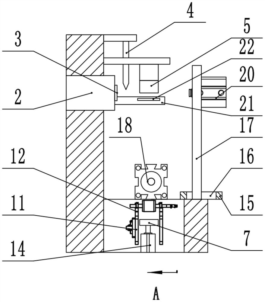
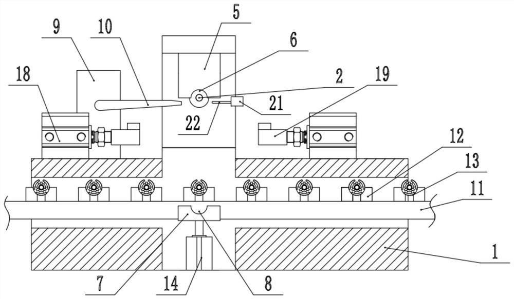
[0029] The reference signs in the drawings of the description include: workbench 1, servo motor 2, matching block 3, welding head 4, upper mold 5, first groove 6, lower mold 7, second groove 8, air pump 9, guide Air pipe 10, conveyor chain 11, bracket seat 12, third groove 13, first telescopic cylinder 14, load plate 15, slideway 16, support plate 17, third telescopic cylinder 18, block 19, second telescopic cylinder 20 , positioning rod 21, positioning block 22.

[0030] The embodiment is basically as attached figure 1 with attached figure 2 Shown: The rotor spot welding device includes a workbench 1, a servo motor 2 is fixed by bolts on the bottom of the workbench 1, the drive shaft of the servo motor 2 is parallel to the horizontal plane, and the drive shaft of the servo motor 2 is coaxially keyed and fixed with a mating block 3 , The end of the mating block 3 has a keyway mat...


PUM


Abstract

The invention relates to the technical field of motor rotor welding, and particularly discloses a rotor spot welding device. The rotor spot welding device comprises a workbench, wherein a driving motor capable of intermittently rotating is fixed to the workbench; the output end of the driving motor can be matched with a rotor; a welding head is fixed to the workbench and located above the output end of the driving motor; an upper die is fixed to the side wall of the workbench; a first groove is formed in the bottom end of the upper die; the side wall of the workbench is fixedly connected with a conveying mechanism for conveying the rotor; a first telescopic mechanism which vertically stretches out and draws back is arranged under the conveying mechanism; the free end of the first telescopic mechanism is fixedly connected with a lower die used for being matched with the upper die; a second groove is formed in the top of the lower die; and a space formed by the first groove and the second groove can accommodate the space of the rotor. According to the rotor spot welding device, the technical problem that the operation steps of the spot welding process of the rotor are complex is solved.

Description

technical field [0001] The invention relates to the technical field of motor rotor welding, and specifically discloses a rotor spot welding device. Background technique [0002] The rotor is the rotating part of the generator and is an important component of the generator. The yoke of the rotor is usually stacked by punching several steel plates, and then fixed by multiple axial welding along the circumference of the rotor laminations. [0003] At present, the commonly used method of welding rotor laminations is to manually use a welding torch to perform multi-pass welding. After one welding is completed, the welding torch needs to be rotated at a specific angle to perform the next welding until the welding is completed. The welding efficiency of this welding method is low, and the welding quality is unstable during manual operation, so it is difficult to meet the requirements of mass production. Contents of the invention [0004] The purpose of the present invention is ...

Claims


Application Information

Patent Timeline
Patent Type & Authority Applications(China)
IPC IPC(8): B23K11/11B23K11/36
CPCB23K11/11B23K11/36
Inventor 周建章周兵
Owner 重庆宝优机电有限公司
Why Eureka
Try Eureka