
Scribing device for scribing platform

A scribing device and a scribing platform technology, applied to workshop equipment, manufacturing tools, etc., can solve the problems of affecting the working environment of surrounding staff, affecting the processing quality of the next process, and reducing the accuracy of scribing, so as to reduce toxic gases, Improved usability and improved accuracy

Inactive Publication Date: 2021-06-15
北京嘉顺鸿科科技有限公司
View PDF0 Cites 2 Cited by
  • Summary
  • Abstract
  • Description
  • Claims
  • Application Information

AI Technical Summary

Problems solved by technology

[0002] The existing scribing plate used for the scribing platform for machining has a relatively simple structure. When scribing a workpiece with a smooth surface, it is necessary to smear a dye on the workpiece (the dye is composed of chromosomes and volatile raw materials, such as Gasoline, alcohol, ethanol, etc.), which makes the scribing more clear, but it needs to be applied on a large area when smearing, which is wasteful and has a strong smell, which affects the working environment of the surrounding staff, and the existing scribing plate Generally, the hinge of the two moving rods is realized through the connecting pin, so that the limit of the moving rod is realized by knocking the connecting pin, so that the two moving rods lean against each other, and the limit of the moving angle of the moving rod is realized through friction. In this way, in the process of scribing, there will be a slight movement of the moving rod, resulting in a decrease in the accuracy of scribing, which will affect the processing quality of the next process

Method used


Image

  • Scribing device for scribing platform
  • Scribing device for scribing platform
  • Scribing device for scribing platform

Examples


Embodiment Construction

[0021] The present invention is described in further detail now in conjunction with accompanying drawing. These drawings are all simplified schematic diagrams, which only illustrate the basic structure of the present invention in a schematic manner, so they only show the configurations related to the present invention.

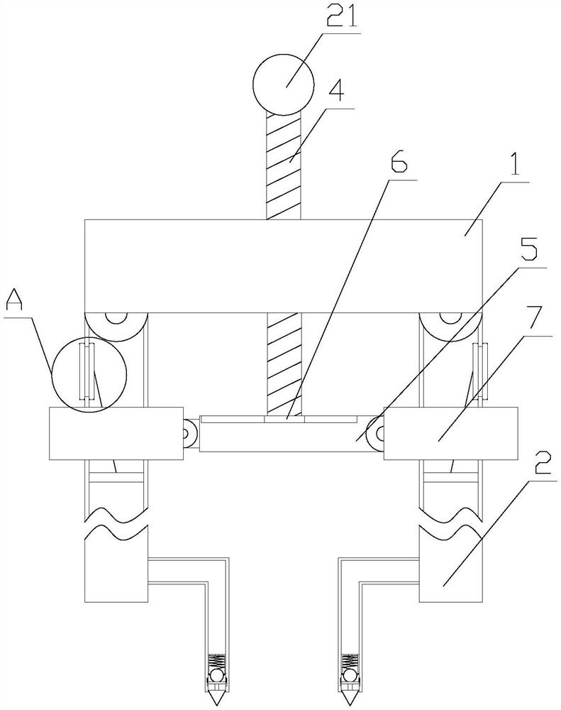
[0022] Such as Figure 1-4 As shown, a scribing device for a scribing platform includes a fixed block 1, a moving mechanism and a smearing mechanism, the fixed block 1 is arranged horizontally, the moving mechanism is arranged on the fixed block 1, and the smearing mechanism Set under the fixed block 1;

[0023] The moving mechanism includes a moving assembly and a driving assembly. There are two moving assemblies, and the two moving assemblies are respectively arranged at the two ends below the fixed block 1. The moving assembly includes a moving rod 2 and a pole 3. The moving assembly Rod 2 is vertically arranged below fixed block 1, and described strut 3 ...


PUM


Abstract

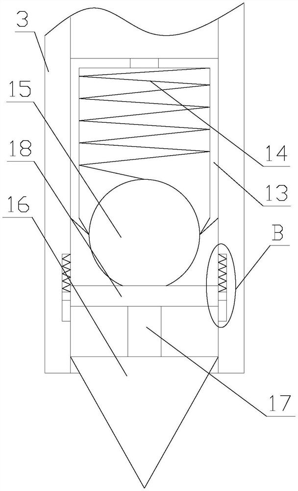
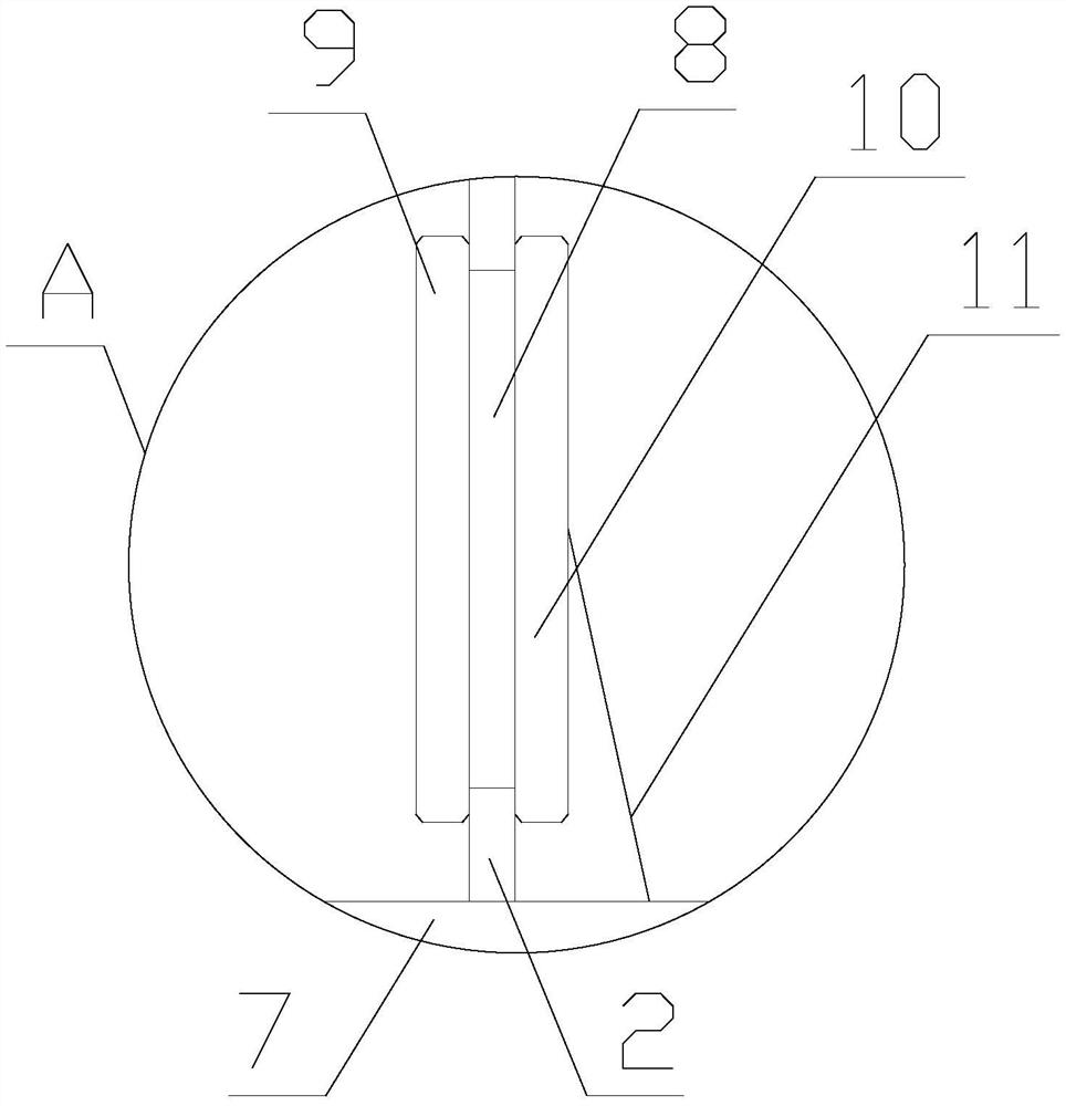
The invention relates to a scribing device for a scribing platform. The scribing device for the scribing platform comprises a fixed block, a moving mechanism and a smearing mechanism, the moving mechanism comprises a moving assembly and a driving assembly, and the smearing mechanism comprises a feeding assembly and a discharging assembly. According to the scribing device for the scribing platform, a lead screw rotates to achieve moving of a moving rod, the moving rod is restored through restoring force of a torsional spring, so that the moving rod better abuts against lantern rings, a telescopic rod between the two lantern rings is always in a tightened state, the lead screw is limited, the accuracy of the moving distance of the moving rod is improved, the scribing precision is improved, and the quality is improved; and a main body is smeared in a positioned manner through the smearing mechanism, dye can slide down along the outer wall of an ejector pin while the ejector pin moves, and therefore fixed-point dyeing of the main body is achieved, the cost is saved, meanwhile, toxic gas generated by dye volatilization is reduced, the working environment of workers is improved, and the use practicability is improved.

Description

technical field [0001] In particular, the invention relates to a scribing device for a scribing platform. Background technique [0002] The existing scribing plate used for the scribing platform for machining has a relatively simple structure. When scribing a workpiece with a smooth surface, it is necessary to smear a dye on the workpiece (the dye is composed of chromosomes and volatile raw materials, such as Gasoline, alcohol, ethanol, etc.), which makes the scribing more clear, but it needs to be applied on a large area when smearing, which is wasteful and has a strong smell, which affects the working environment of the surrounding staff, and the existing scribing plate Generally, the hinge of the two moving rods is realized through the connecting pin, so that the limit of the moving rod is realized by knocking the connecting pin, so that the two moving rods lean against each other, and the limit of the moving angle of the moving rod is realized through friction. In this ...

Claims


Application Information

Patent Timeline
Patent Type & Authority Applications(China)
IPC IPC(8): B25H7/04
CPCB25H7/04
Inventor 刘晓思
Owner 北京嘉顺鸿科科技有限公司
Learn More