Adjacent rack rail mounting and adjusting appliance for rack rail railway

A technology for installation and adjustment of racks, which is applied in the directions of roads, tracks, paved tracks, etc., can solve the problems that the longitudinal pitch and other position parameters of two adjacent racks cannot be accurately and quickly detected, and the construction efficiency is low. Achieve the effect of improving work efficiency, convenient and fast movement

Active Publication Date: 2021-06-15
CHINA RAILWAY ERYUAN ENG GRP CO LTD
View PDF15 Cites 2 Cited by
  • Summary
  • Abstract
  • Description
  • Claims
  • Application Information

AI Technical Summary

Problems solved by technology

[0005] The purpose of the present invention is to solve the problem that the longitudinal tooth pitch and other position parameters of two adjacent rack rails cannot be accurately and quickly performed when the rack rails are installed in the prior art. In order to solve the problems of detection and low construction efficiency, a device for adjusting the installation of adjacent racks for rack railways is provided, which is used to assist the installation of racks, so that the installation of racks is fast, efficient and accurate

Method used


Image

  • Adjacent rack rail mounting and adjusting appliance for rack rail railway
  • Adjacent rack rail mounting and adjusting appliance for rack rail railway
  • Adjacent rack rail mounting and adjusting appliance for rack rail railway

Examples


Embodiment 1

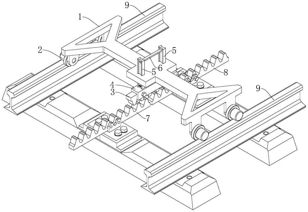
[0033] Adjacent rack rail installation adjustment device for a rack railway, such as Figure 1-Figure 4 , including the wheel hub 2 of the walking module, the frame 1 of the load-bearing module and the working module.

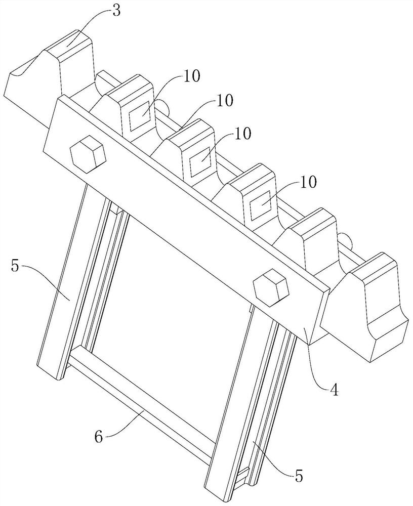
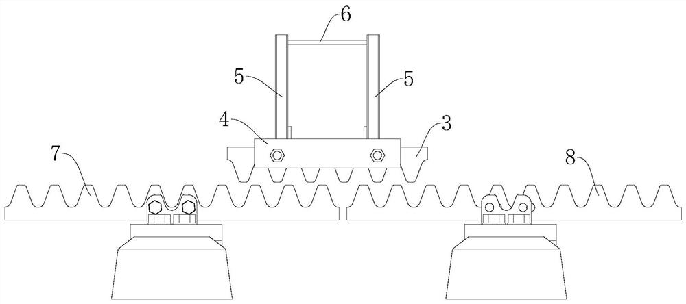
[0034] Specifically, such as figure 1 , 2 , the working module is located below the frame 1, corresponding to the position of the rack, and includes an engaging rack 3, a base 4 and two opposite guide rails 5. The meshing rack 3 is fixed in the through-slot structure of the base 4 by fastening bolts upside down, and the meshing rack 3 is used to simultaneously engage with the installation rack (that is, the rack): the first rack 7 and the second rack 8; Two oppositely arranged guide rails 5 are arranged on the two ends of the upper part of the base 4 along the length direction of the base 4, engraved with the same scale mark, and the two slide up and down through two through holes arranged longitudinally on the frame 1; The arrangement is to ensure that the ...

Embodiment 2

[0042] In the actual operation of the cog railway, the repeated action of the cog and the gear on the train will continuously increase the wear of the tooth surface of the cog, especially the teeth near the adjacent cog, which have high vibration frequency and fast wear; when the cog Tooth surface wear to a certain extent will affect the quality of driving operation, and then the rack needs to be replaced. In order to further quantitatively reflect the installation accuracy of the adjacent racks and detect whether the position accuracy of the racks meets the operating requirements after a period of operation, such as image 3 , on several teeth of the meshing rack 3 in embodiment 1, a laser distance measuring sensor 10 is embedded in the tooth surfaces on both sides of each tooth to detect the tooth surface of the meshing rack 3 to the meshing rack tooth surface the distance between. In this way, on the one hand, it can quantitatively reflect the degree of engagement between ...


PUM


Abstract

The invention relates to the field of rack rail detection, in particular to an adjacent rack rail mounting and adjusting appliance for a rack rail railway, which comprises a rack slidably connected with steel rails on two sides and a working module positioned below the rack, the working module comprises a meshing rack, a base and a guide rail, the guide rail is slidably connected with the rack up and down, and the guide rail is fixedly connected to the base; the base is detachably connected with a meshing rack, the meshing rack is used for being meshed with a rack rail to be installed, and the guide rail is used for recognizing the relative height between the meshing rack and the rack; according to the invention, quick longitudinal positioning can be realized, and the longitudinal pitch between two adjacent toothed rails can be adjusted in an auxiliary manner, so that the two adjacent toothed rails can be flatly mounted, the mounting position height meets the travelling crane requirement, the construction is quick and efficient, the positioning is accurate, and the construction efficiency can be improved.

Description

technical field [0001] The invention relates to the technical field of rack rail detection, in particular to an adjacent rack rail installation adjustment device for rack railways. Background technique [0002] The difference between the cog railway and the general track railway is that the cog railway usually adds a rack track (also known as the cog track) in the middle of the general railway track, and the bogie of the corresponding running vehicle is equipped with a gear device that meshes with the rack track , to supplement the wheel-rail adhesion force when the vehicle is climbing or use the gear-rail meshing force instead of the adhesion force to achieve the purpose of driving the rail vehicle to climb the slope; in the construction of the rack railway, the installation of the core component rack is particularly important. [0003] The rack track consists of a large number of prefabricated racks assembled. In order to ensure the assembly quality of all racks after inst...

Claims


Application Information

Patent Timeline
Patent Type & Authority Applications(China)
IPC IPC(8): E01B29/16E01B29/20E01B25/04
CPCE01B29/16E01B29/20E01B25/04E01B2203/017E01B2203/143
Inventor 陈志辉杨吉忠舒睿洪徐家根肖飞知冯读贝代丰陈以庭李忠继陈志贤蒋尧
Owner CHINA RAILWAY ERYUAN ENG GRP CO LTD
Why Eureka
Try Eureka