Eureka AIR delivers breakthrough ideas for toughest innovation challenges, trusted by R&D personnel around the world.

A coupled piston heat exchanger applied to a Stirling machine and its working method

A technology that couples pistons and shell-and-tube heat exchangers. It is applied in the direction of machines/engines, mechanical equipment, engine components, etc. It can solve problems such as the inability to eliminate useless volumes, and achieve the effect of increasing the compression ratio and simplifying the overall structure.

Active Publication Date: 2022-05-17
CHINA UNIV OF MINING & TECH
View PDF4 Cites 0 Cited by
  • Summary
  • Abstract
  • Description
  • Claims
  • Application Information

AI Technical Summary

Problems solved by technology

However, the improvement of the performance of the heat exchanger still cannot eliminate the useless volume brought by the heat exchange tube inside the heat exchanger to the whole machine

Method used


Image

  • A coupled piston heat exchanger applied to a Stirling machine and its working method
  • A coupled piston heat exchanger applied to a Stirling machine and its working method
  • A coupled piston heat exchanger applied to a Stirling machine and its working method

Examples


Embodiment 1

[0046] Embodiment 1: As a compression expansion chamber and a heat exchanger of a Stirling engine or a refrigerator.

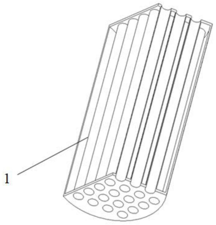
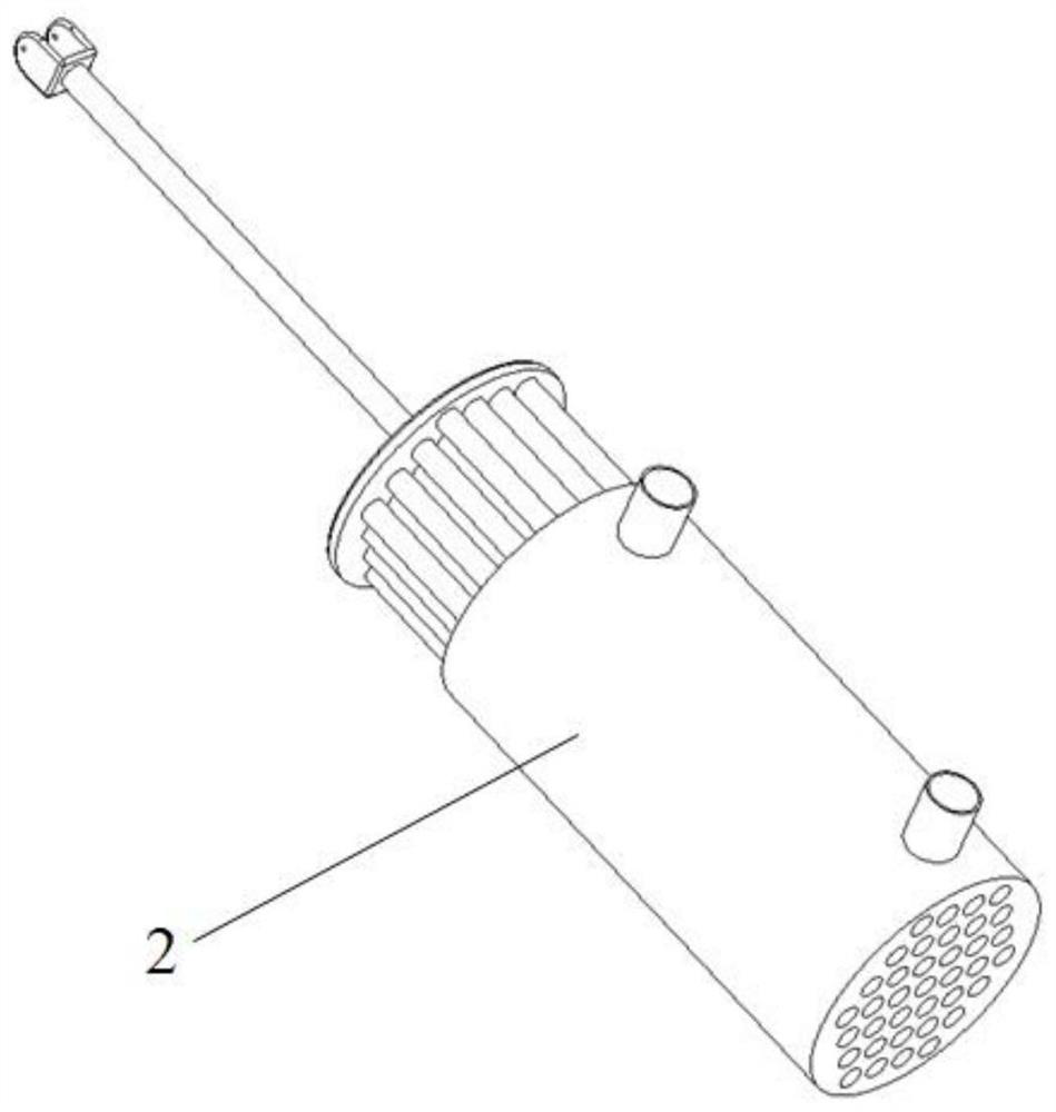
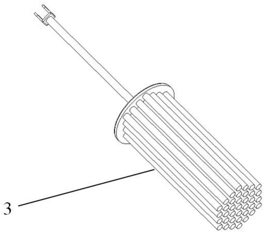
[0047] In the α-type double-piston Stirling machine, it is connected to the crank-connecting rod structure through the back of the circular plate. In a Stirling refrigerator installation, according to Figure 7 As shown in the connection device, the coupling heat exchanger pistons are respectively installed on both sides. Cooling water or other cooling fluid flows through the inlet and outlet of the shell and tube heat exchanger on the right. The left side is the refrigeration end, and the inlet and outlet of the shell-and-tube heat exchanger on the left side are circulated with cooling fluid or working fluid. The two heat exchangers are connected to the regenerator, and the initial position of the crank connecting rod is adjusted to adjust the position of the piston group 3 in the tube side 1 of the heat exchanger. The movement in the tube pass 1, and the ...


PUM


Abstract

The invention discloses a coupled piston heat exchanger and a working method applied to a Stirling machine, belonging to the field of heat exchanger equipment. It includes the shell and tube heat exchanger shell and the honeycomb array piston group. Heat pipe, the honeycomb array piston group includes a linkage metal plate, and its front end is provided with a number of sub-pistons that are equal in number and position to the heat exchange tubes of the shell-and-tube heat exchanger. In each heat exchange tube, the rear end is connected to the power source through a crank connecting rod. It eliminates the useless volume in the heat exchanger, that is, the dead volume, improves the compression ratio of the internal working medium, and makes the working medium cool or heat while compressing and expanding, making the internal working medium cycle closer to the theoretical cycle. In the case of , the more pistons in the piston group, the larger the heat exchange area.

Description

technical field [0001] The invention relates to a coupled piston heat exchanger and a working method applied to a Stirling machine, and is especially suitable for a compression expansion cavity and a cold and hot section heat exchanger and a working method of a Stirling engine or a refrigerator. Background technique [0002] Traditional Stirling refrigerators or Stirling engines are mainly α-type, β-type, and γ-type. Its operation mode basically uses piston movement to ensure the compression and expansion of the internal gas working medium, and relies on the wall of the piston cylinder for simple heat exchange, or connects a separate heat exchanger outside the expansion chamber of the compression chamber for heat exchange. Relying on the wall surface of the piston cylinder for heat exchange is limited by the heat exchange area, so it is difficult to increase the heat exchange capacity, which leads to the inability to improve the efficiency of the whole machine; a separate he...

Claims


Application Information

Patent Timeline
Patent Type & Authority Patents(China)
IPC IPC(8): F02G1/044F02G1/055F02G1/053
CPCF02G1/044F02G1/055F02G1/053F02G2270/40Y02E10/46
Inventor 王焕光汤雨明张碧林刘猛朱帅包云皓
Owner CHINA UNIV OF MINING & TECH
Why Eureka
Eureka Blog
Learn More