Light guide plate and lattice point distribution method thereof

A light guide plate and dot technology, applied in light guides, optics, optical components, etc., can solve problems such as poor light output from the light guide plate

Active Publication Date: 2021-06-15
DONGGUAN YUANLI ELECTRONICS TECH
View PDF8 Cites 3 Cited by
  • Summary
  • Abstract
  • Description
  • Claims
  • Application Information

AI Technical Summary

Problems solved by technology

[0004] In view of the above-mentioned related technologies, the inventor believes that the white spots or foreign objects formed in the processing process will cause fringe interference or bright spots when the light guide plate emits light, and it is difficult to cover these white spots or foreign objects through the above-mentioned method of distribution, so that the light guide plate Poor lighting effect

Method used


Image

  • Light guide plate and lattice point distribution method thereof
  • Light guide plate and lattice point distribution method thereof
  • Light guide plate and lattice point distribution method thereof

Examples


Embodiment 1

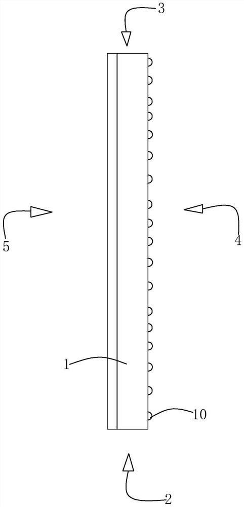
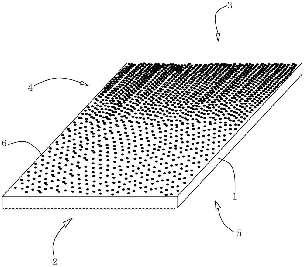
[0055] refer to figure 1 , a light guide plate, comprising a light guide plate body 1, the light guide plate body is made of PMMA material. The two ends of the length direction of the light guide plate body 1 are the light incident side 2 and the light exit side 3 respectively, the light incident side 2 is the incident direction of the light source, and the two sides in the thickness direction of the light guide plate body 1 are the reflective surface 4 and the light exit surface 5 respectively. , wherein the light emitting surface 5 is the effective viewing area of ​​the light guide plate body 1 .

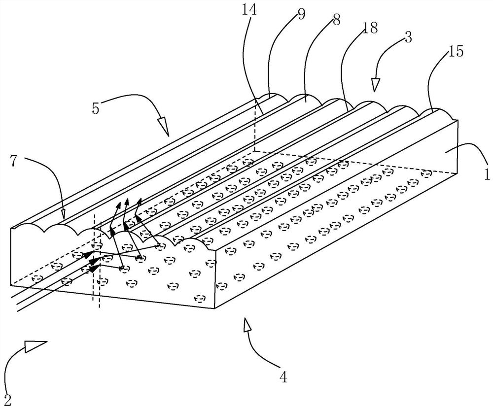
[0056] refer to figure 2 The light emitting surface 5 of the light guide plate body 1 is provided with a light emitting groove 7, the light emitting groove 7 is arranged along the length direction of the light guide plate body 1 and is consistent with the incident direction of the light source, and the depth of the light emitting groove 7 must be greater than or equal to 3um. I...

Embodiment 2

[0065] Embodiment 2: refer to Figure 5 , and the difference from Example 1 is that the reflective surface 4 is provided with a reflective groove 10, the reflective groove 10 is arranged along the length direction of the light guide plate body 1 and is consistent with the incident direction of the light source, and the depth of the reflective groove 10 is less than or equal to 4um . In this embodiment, multiple reflective slots 10 may be provided, and the multiple reflective slots 10 are arranged sequentially along the width direction of the light guide plate, so that the reflective surface 4 forms multiple reflective curved surfaces 11 that reflect or scatter light from the light source.

[0066] A plurality of reflective curved surfaces 11 are arranged sequentially along the length direction of the light guide plate body 1 . The opposite sides of two adjacent reflective curved surfaces 11 can be superimposed and connected to form a third coincident side 16 and a fourth coin...

Embodiment 3

[0070] Embodiment 3: refer to Figure 7 , different from Embodiment 1, the two sides in the length direction of the first curved surface 8 and the second curved surface 9 are respectively the first curve 12 and the second curve 13, the radius of curvature of the first curve 12 and the radius of curvature of the second curve 13 The radius of curvature is small, and the radius of curvature of the first curve 12 and the radius of curvature of the second curve 13 are both within 0-25um. Therefore, the radius of curvature of the first curved surface 8 and the second curved surface 9 gradually increases from the light incident side 2 to the light exit side 3 along the length direction of the light guide plate, so that the light receiving surface of the first curved surface 8 and the second curved surface 9 can be along The length direction of the light guide plate body gradually increases, so that the light source light is more refracted as the light source light is closer to the li...


PUM


Abstract

The invention relates to the field of light guide plate production and processing, in particular to a light guide plate and a lattice point distribution method thereof. The light guide plate comprises a light guide plate body, wherein the two side surfaces of the light guide plate body in the length direction are arranged to be a light inlet side and a light outlet side respectively, the two side surfaces of the light guide plate body in the width direction are set to be a light outlet surface and a reflecting surface respectively, a plurality of light-emitting cutting grooves are formed in the light-emitting surface and are sequentially arranged in the width direction of the light guide plate body, a plurality of rows of lattice points are arranged on the reflecting surface in the width direction of the light guide plate body, the distance between every two adjacent rows of lattice points is equal to the distance between every two adjacent light-emitting cutting grooves, the distances between every two adjacent rows of lattice points are not equal, meanwhile, a two-dimensional coordinate system is established, the lattice points are distributed in the X-axis direction and randomly distributed at intervals in the Y-axis direction, the lattice points are distributed in a repulsive mode according to the repulsive force principle, a plurality of brightening stripes are formed when the light guide plate emits light, and therefore white dots or foreign matter in the light guide plate is covered.

Description

technical field [0001] The present application relates to the field of production and processing of light guide plates, in particular to a light guide plate and a dot arrangement method thereof. Background technique [0002] The light guide plate is one of the main components of the backlight module with side light input, and converts the point light generated by the light-emitting diodes on one side of the light guide plate into uniform surface light, which is used as a plane light source required by the liquid crystal display. [0003] In the conventional design of the light guide plate, a plurality of dots are generally set on the reflective surface of the light guide plate, and the dots are distributed in a regular or random manner. Through such a dot distribution, the light from the light source is refracted on the light incident side and enters the light guide. In the light panel body, the dots can refract, reflect and scatter the light from the light source in multipl...

Claims


Application Information

Patent Timeline
Patent Type & Authority Applications(China)
IPC IPC(8): G02B6/00
CPCG02B6/0038G02B6/0043G02B6/0055G02B6/0058
Inventor 黄爱群阮绪红张晓睿
Owner DONGGUAN YUANLI ELECTRONICS TECH
Why Eureka
Try Eureka