A dust-absorbing insulation structure for a distribution box

A technology of insulating structure and distribution box, applied in substation/distribution device casing, electrical components, circuit devices, etc., can solve problems such as affecting the working quality and service life of electronic devices, increasing labor intensity of workers, and troublesome unpacking and cleaning. , to achieve the effect of improving the efficiency of dust removal, strong practicability and market competitiveness, and low cost of transformation

Active Publication Date: 2021-12-28
SHANDONG UNIV +1
View PDF8 Cites 0 Cited by
  • Summary
  • Abstract
  • Description
  • Claims
  • Application Information

AI Technical Summary

Problems solved by technology

[0002] The distribution box is a commonly used device in power equipment. Generally, there are more electronic components and circuits in the distribution box. During the operation of the distribution box, these electronic components and circuits will generate a continuous electromagnetic field after being energized. This has led to the fact that electronic components and circuits are extremely easy to absorb dust under working conditions, and the accumulation of dust will seriously affect the working quality and service life of electronic devices
[0003] In order to solve the above technical problems, those skilled in the art generally carry out regular manual unpacking and cleaning to remove the dust accumulated in the distribution box during the use of the distribution box; however, this regular unpacking and cleaning passively is also very Trouble, greatly increased the labor intensity of workers

Method used


Image

  • A dust-absorbing insulation structure for a distribution box
  • A dust-absorbing insulation structure for a distribution box
  • A dust-absorbing insulation structure for a distribution box

Examples


Embodiment 1

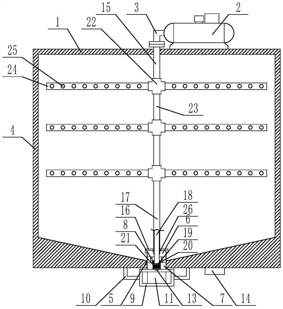
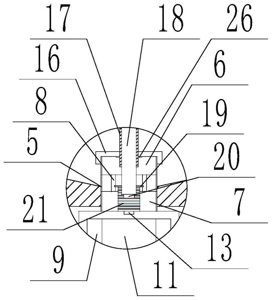
[0045] During the implementation of the technical solution of the present application, the initial state of the device is as follows figure 1 As shown, at this time, the pneumatic rod is in the rising state under the action of the spring, the magnet is far away from the Hall switch, the Hall switch is disconnected, and the fan does not work when the power is off; The controller starts the electric air pump, at this time the electric air pump pumps high-pressure air into the air intake pipe through the L-shaped pipe, the high-pressure air enters the connecting pipe and the exhaust pipe through the four-way pipe, and the high-pressure air is blown in through several air holes in the exhaust pipe The distribution box blows up the dust in the distribution box, and the blown dust finally falls on the bottom surface of the insulating inner shell and slides along the bottom surface to the vicinity of the suction pipe. At the same time, the high-pressure airflow enters the next four T...

Embodiment 2

[0047] The magnet on the lower end face of the pneumatic rod is removed, and the Hall switch is replaced by a button switch or a pressure switch, and the others are the same as in Embodiment 1.


PUM


Abstract

The invention discloses a dust-absorbing insulation structure of a distribution box, which comprises a distribution box, an electric air pump is fixedly installed on the top of the distribution box, an L-shaped pipe is fixedly installed at the air outlet of the electric air pump, and the L-shaped pipe One end is docked with the air outlet of the electric air pump, and the other end points vertically downward to the distribution box. The inner surface of the distribution box is fixed with an insulating inner shell, and the bottom surface of the insulating inner shell is an inverted conical surface. The bottom surface of the insulating inner shell is provided with a dust suction pipe, the dust suction pipe is located at the lowest point of the bottom surface of the insulating inner shell, and the dust suction pipe connects the inner cavity of the distribution box with the outside. pipe and the lower end pipe, the lower edge of the upper end pipe is connected to the upper edge of the lower end pipe through several connecting plates, the upper end pipe is located in the inner cavity of the distribution box, and the lower edge of the lower end pipe protrudes downward bottom of the box. The beneficial effect of the invention is that the structural design is reasonable and the energy consumption is effectively reduced.

Description

technical field [0001] The invention relates to the technical field of electric equipment, in particular to a dust-absorbing insulation structure for a distribution box. Background technique [0002] The distribution box is a commonly used device in power equipment. Generally, there are more electronic components and circuits in the distribution box. During the operation of the distribution box, these electronic components and circuits will generate a continuous electromagnetic field after being energized. This has led to the fact that electronic components and circuits are extremely easy to absorb dust under working conditions, and the accumulation of dust will seriously affect the working quality and service life of electronic devices. [0003] In order to solve the above technical problems, those skilled in the art generally perform regular manual unpacking and cleaning to remove the accumulated dust in the distribution box during the use of the distribution box; however,...

Claims


Application Information

Patent Timeline
Patent Type & Authority Patents(China)
IPC IPC(8): H02B1/28H02B1/56H02J13/00B08B5/04
CPCH02B1/28H02B1/56H02J13/00022B08B5/04Y04S40/126Y02B90/20
Inventor 刘彧挥燕永振李立广张校玮
Owner SHANDONG UNIV
Why Eureka
Try Eureka