Novel plate laser cutting machine

A laser cutting machine, a new type of sheet metal technology, applied in laser welding equipment, welding/cutting auxiliary equipment, auxiliary welding equipment, etc., can solve the problems of trouble to take out the sheet, offset cutting position, waste of physical strength, etc., to achieve the effect of convenient collection

Active Publication Date: 2021-06-18
赣州市恒邦金属制品有限公司
View PDF16 Cites 2 Cited by
  • Summary
  • Abstract
  • Description
  • Claims
  • Application Information

AI Technical Summary

Problems solved by technology

[0005] In order to overcome the disadvantages that manual control of the laser cutting machine not only requires a lot of physical strength, but also the moving position is not easy to control, it is easy to make the cutting position shift, and it is troublesome to take out the plate after cutting. The technical problem to be solved by the present invention is: to provide a A new type of sheet metal laser cutting machine that automatically moves and cuts and is convenient for fixing and taking sheets

Method used


Image

  • Novel plate laser cutting machine
  • Novel plate laser cutting machine
  • Novel plate laser cutting machine

Examples


Embodiment 1

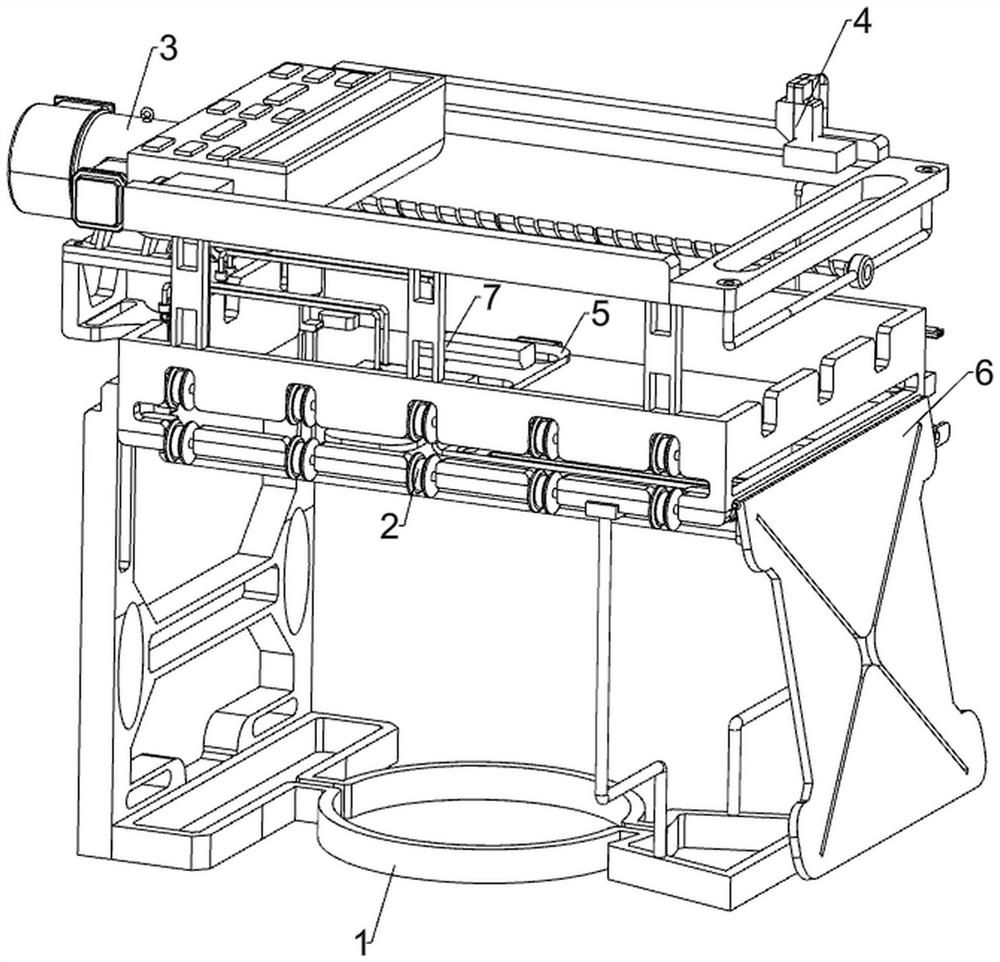
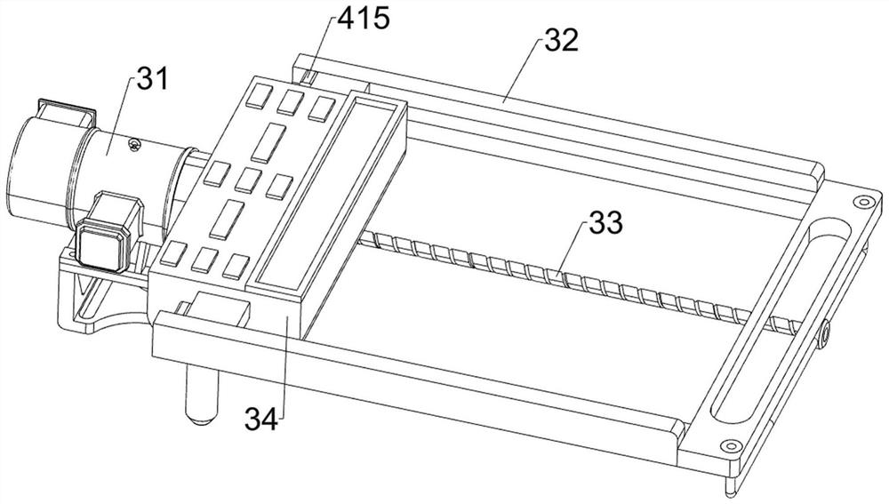
[0029] A new type of plate laser cutting machine, such as Figure 1-5 As shown, it includes a frame 1, a feeding assembly 2, a cutting assembly 3 and a pushing assembly 4, the frame 1 is provided with a feeding assembly 2, the feeding assembly 2 is provided with a cutting assembly 3, and the frame 1 is provided with a Push material assembly 4 is arranged.

[0030] When it is necessary to laser cut the plate, put the plate into the feeding component 2, then start the cutting component 3, and the cutting component 3 will perform laser cutting on the plate. After the cutting is completed, control the cutting component 3 to operate in reverse, and then drive The material assembly 4 is operated, so that the cut boards will be pushed out, which is convenient for the staff to take out the cut boards. After pushing out, the pusher assembly 4 will automatically reset, and then repeat the above process. When all the boards are completely cut, Close the cutting assembly 3 and get final ...

Embodiment 2

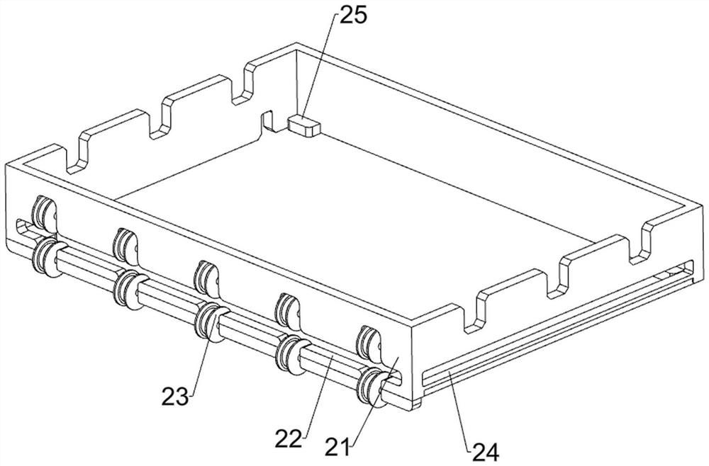
[0038] On the basis of Example 1, such as figure 1 , Figure 6 , Figure 7 and Figure 8 As shown, a support assembly 5 is also included, and the support assembly 5 includes an L-shaped slide plate 51, a support plate 52, a vertical plate 53 and a special-shaped plate 54, and the rear side of the placement frame 21 is slidably provided with an L-shaped slide plate 51, and the L-shaped slide plate The front side of 51 is connected with support plate 52 , and the lower side of support plate 52 is provided with riser 53 , is connected with special-shaped plate 54 between riser 53 and connecting plate 42 .

[0039] When the board is placed on the placement block 25, the board will be dragged by the support plate 52, which can effectively prevent the board from falling halfway when cutting the board, thereby affecting the cutting of the board. The support plate 52 and the L-shaped slide plate 51 move to the right, so that the plate is not easy to fall when it is pushed out.

[...


PUM


Abstract

The invention relates to a cutting machine, in particular to a novel plate laser cutting machine. The novel plate laser cutting machine aims to achieve the technical effects that automatic moving cutting is achieved, and plates are convenient to fix and take for use. The novel plate laser cutting machine comprises a rack; a feeding assembly which is mounted on the rack; a cutting assembly which is mounted on the feeding assembly; and a pushing assembly which is mounted between the feeding assembly and the cutting assembly. According to the novel plate laser cutting machine, the pushing assembly is arranged, so that cut plates can be pushed out of a discharging opening, and then workers can conveniently take out the cut plates; and a supporting assembly is arranged, so that the situation that cutting of the plates is affected due to midway falling of the plates during cutting can be effectively prevented.

Description

technical field [0001] The invention relates to a cutting machine, in particular to a novel plate laser cutting machine. Background technique [0002] The laser cutting machine uses a high-power-density laser beam to irradiate the material to be cut, so that the material is quickly heated to the vaporization temperature, evaporates to form holes, and as the beam moves to the material, the holes continuously form narrow slits to complete the cutting of the material. A cutting machine. [0003] The general laser cutting machine needs manual control. When the laser cutting machine needs to be used, the plate is manually fixed, and then the laser cutting machine is controlled to move, so as to cut the plate. Manually controlling the laser cutting machine not only requires more physical strength, but also moves the position. It is not easy to control, it is easy to make the cutting position shift, and it is troublesome to take out the plate after cutting. [0004] Therefore, it...

Claims


Application Information

Patent Timeline
Patent Type & Authority Applications(China)
IPC IPC(8): B23K26/70B23K37/04B23K26/38
CPCB23K26/702B23K37/0435B23K26/38
Inventor 刘运辉
Owner 赣州市恒邦金属制品有限公司
Why Eureka
Try Eureka