
Truss type intelligent drilling equipment

A kind of drilling equipment and truss-type technology, which is applied in the field of truss-type intelligent drilling equipment, can solve problems such as inability to effectively complete the drilling process, part binding, and easy slippage, so as to avoid slippage, increase fixity, and shorten spacing Effect

Active Publication Date: 2021-06-18
东莞市佑高金属制品有限公司
View PDF14 Cites 0 Cited by
  • Summary
  • Abstract
  • Description
  • Claims
  • Application Information

AI Technical Summary

Problems solved by technology

[0005]In order to solve the above-mentioned technology, when drilling, the low-speed rotating drill bit continuously exerts a downward force on the workpiece, and because the workpiece is placed on the platform The end surface is smooth, so that when the equipment drills a part with a flat or smooth lower end surface, there is no lateral fixation between the part and the placement platform, so that the part cannot be restrained during drilling, so that the part is in the drill bit. It is easy to form slippage under the continuous application of force, and the problem that the drilling process cannot be effectively completed

Method used


Image

  • Truss type intelligent drilling equipment
  • Truss type intelligent drilling equipment
  • Truss type intelligent drilling equipment

Examples


Embodiment 1

[0029] as attached figure 1 to attach Image 6 Shown:

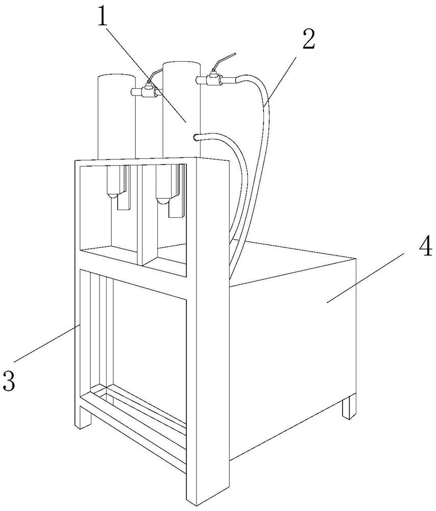
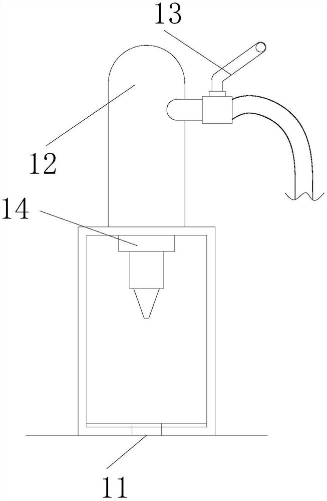
[0030] The invention provides a truss-type intelligent drilling equipment, the structure of which includes a drilling mechanism 1, a hydraulic pipe 2, a bracket 3, and an equipment cabin 4. The drilling mechanism 1 is embedded and installed directly above the bracket 3. The hydraulic pressure The pipe 2 is nested and connected to the outer end surface of the equipment compartment 4, and the bracket 3 is fixed on the outer end surface of the equipment compartment 4 by welding, and the equipment compartment 4 is located under the right side of the drilling mechanism 1; the drilling mechanism 1 includes Place platform 11, lifting pipe 12, handle 13, and drilling tool 14. The placing platform 11 is embedded and installed directly below the drilling tool 14. The right end surface of the lifting pipe 12 is nested and connected to the hydraulic pipe 2. The handle 13 is inlaid on the upper right side of the drilling tool 14, an...

Embodiment 2

[0038] as attached Figure 7 To attach Figure 9 Shown:

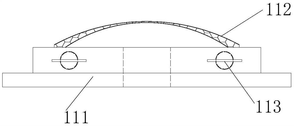
[0039] Wherein, the adsorption mechanism 113 includes a ball 131, an inlay groove 132, a threaded rotating rod 133, and a knob 134. The ball 131 is movably mounted on the inner end surface of the inlaid groove 132, and the inlaid groove 132 is fixedly mounted on the threaded rotating rod. The lower end surface of the rod 133, the threaded rotating rod 133 is inlaid directly above the knob 134, the knob 134 is located directly below the inlay groove 132, and the balls 131 are arranged in two rows up and down with a distance between them, which can The rolling effect formed by the balls 131 reduces the surface friction between the embedding groove 132 and the end surface of the embedding plate 111 .

[0040] Wherein, the threaded rotating rod 133 includes a magnetic attraction mechanism 331, a rotating shaft 332, a screw blade 333, and a rotating rod 334. The magnetic attraction mechanism 331 is embedded and engaged on ...


PUM


Abstract

The invention discloses truss type intelligent drilling equipment. The truss type intelligent drilling equipment structurally comprises a drilling mechanism, a hydraulic pipe, a support and an equipment cabin; the drilling mechanism is fixedly installed over the support in an embedded mode; the hydraulic pipe is connected to the outer end face of the equipment cabin in a nested mode; the support is fixed to the outer end face of the equipment cabin through welding; the equipment cabin is located below the right side of the drilling mechanism; the drilling mechanism comprises a storage platform, a lifting pipe, a handle and a drilling tool; the storage platform is fixedly installed under the drilling tool in an embedded mode; the right end face of the lifting pipe is connected with a hydraulic pipe in a nested mode; the handle is embedded at the upper portion of the right side of the drilling tool; and the drilling tool is located under the lifting pipe. When the drilling tool drives a part to rotate in a drilling process, a rubber sheet is driven to form pulling, buffering is formed on sinking rotation force of the drilling tool, the surface of the lower end of the part is better fixed through deformation generated by a rubber ring and the rubber sheet, and therefore the problems of slipping and the like in the drilling process are effectively avoided.

Description

technical field [0001] The invention belongs to the field of drilling, and more specifically relates to a truss type intelligent drilling equipment. Background technique [0002] Intelligent drilling equipment is a kind of drill bit that rotates at a low speed under the pressure of the hydraulic controller through the scanning and fixed point of the workpiece when turning the hole by using the electronic calibration equipment and the hydraulic controller. Embedded downward, automatic processing can be formed through electronic control of the terminal. [0003] Based on the above inventors' discovery, the existing methods mainly have the following disadvantages, such as: when drilling, the drill bit rotating at a low speed continuously exerts a downward force on the workpiece, and because the workpiece is placed on the platform The end surface is smooth, so that when the equipment drills a part with a flat or smooth lower end surface, there is no lateral fixation between the...

Claims


Application Information

Patent Timeline
IPC IPC(8): B23Q3/06B23Q5/26B23Q11/00
CPCB23Q5/26B23Q3/062B23Q11/00
Inventor 刘生玉
Owner 东莞市佑高金属制品有限公司
Learn More