

Anti-blocking concrete pipe pile material making and pouring device
A concrete pipe pile and anti-blocking technology, which is applied in the field of building material processing, can solve the problems of blockage at the discharge port and reduce production efficiency, and achieve the effects of preventing blockage, reducing discharge efficiency, and improving discharge efficiency
- Summary
- Abstract
- Description
- Claims
- Application Information
AI Technical Summary
Problems solved by technology
Method used
Image

Examples
Embodiment 1
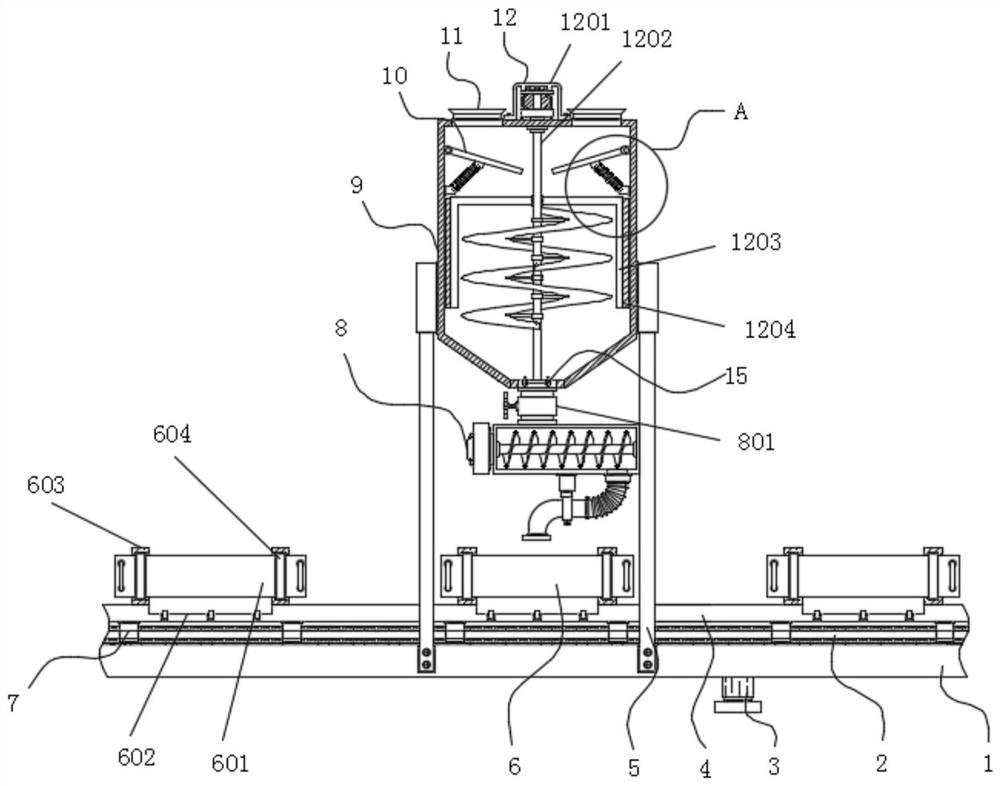
[0035] Example 1: See Figure 1-7 , an anti-clogging concrete pipe pile material pouring device, comprising a base 1, a transmission plate 4 and a material preparation tank 9, the transmission plate 4 is arranged on the top of the base 1, and the two sides of the base 1 are respectively fixedly connected with support columns 5 , the material making tank 9 is fixedly connected to the top of the supporting column 5, and the top of the transmission plate 4 is provided with a structure 6 that is convenient to limit and take. A buffer feeding structure 10 is provided, and a uniform anti-blocking feeding mechanism 8 is provided at the bottom of the material making tank 9. The two sides of the top of the material making tank 9 are respectively fixedly connected with feeding ports 11, between the base 1 and the transmission plate 4 Equipped with a convenient transmission mechanism;
[0036] Stirring and scraping mechanism 12 is made up of frequency conversion motor 1201, stirring rod...
Embodiment 2
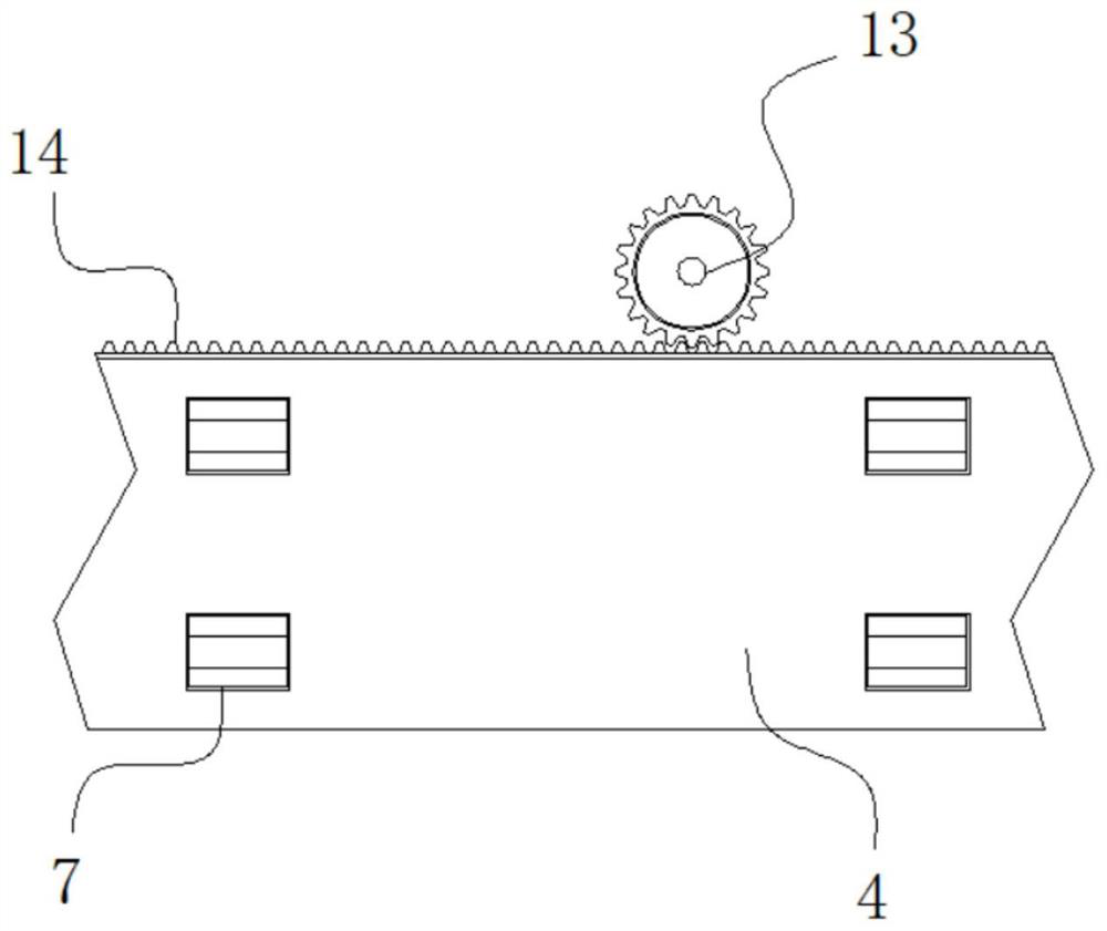
[0039] Embodiment 2: The convenient transmission mechanism includes a slide rail 2, the slide rail 2 is fixedly connected to the two ends of the top of the base 1 respectively, the two ends of the bottom of the transmission plate 4 are respectively fixedly connected to the slider 7, and the rear end of the transmission plate 4 is fixedly connected to a A rack plate 14, a stepper motor 3 is fixedly connected to one side of the rear end of the base 1, the model of the stepper motor 3 can be XC866, and the output end of the stepper motor 3 is fixedly connected to a drive gear 13;
[0040] The driving gear 13 and the rack plate 14 are in the same horizontal plane, and the gear block outside the driving gear 13 is meshed with the tooth block at the rear end of the rack plate 14;
[0041] The slider 7 is embedded in the outside of the slide rail 2, and a sliding connection is formed between the slider 7 and the slide rail 2;
[0042] Specifically, such as figure 1 , figure 2 and ...
Embodiment 3
[0043] Embodiment 3: The structure 6 is convenient for limiting and taking. The front end of the rear baffle 603 is provided with a front baffle 601, and the placement groove 602 is arranged inside the top of the transmission plate 4. The inside of the placement groove 602 is movably connected with a roller 606, and the two sides of the front end of the rear baffle 603 are fixedly connected with inserts. Groove 604, handles 605 are fixedly connected to both sides of the front end of the front baffle 601;
[0044] Both sides of the front baffle 601 are embedded in the interior of the slot 604, the placement grooves 602 are arranged at equal intervals inside the top of the transmission plate 4, and the front baffle 601 and the rear baffle 603 are arranged in concentric circles;
[0045] Specifically, such as figure 1 and Figure 4 As shown, when in use, the mold is placed inside the placement slot 602, and then both sides of the front baffle 601 are embedded in the inside of t...
PUM
 Abstract
Description
Claims
Application Information