
A printed circuit board silk screen scraper assembly and solder resist ink filling system

A technology for printing circuit and solder mask ink, applied in printing, printing machine, rotary printing machine, etc., can solve the problems of poor quality of printed circuit board, scratched screen, affecting production efficiency, etc., so as to avoid affecting production, Avoid damage to the stencil, the effect of simple structure

Active Publication Date: 2021-07-20
四川英创力电子科技股份有限公司
View PDF5 Cites 0 Cited by
  • Summary
  • Abstract
  • Description
  • Claims
  • Application Information

AI Technical Summary

Problems solved by technology

[0003] In the prior art, the solder resist ink is usually poured directly on the screen printing screen during silk screen printing, and then scraped with a scraper to achieve the purpose of screen printing, and most of the prior art uses manual addition of solder resist ink, that is, the operator adds the solder resist ink on the screen printing screen. Observe the amount of ink on the screen at any time during the process. When the solder resist ink is insufficient, stop the operation of the equipment, and then add it manually. The process of adding solder resist ink will greatly affect production efficiency, and if the operator does not add solder resist ink in time, it will be Due to the lack of solder resist ink in the stencil, the quality of the printed circuit board is poor, and the stencil may even be scratched due to the lack of solder resist ink on the stencil.

Method used


Image

  • A printed circuit board silk screen scraper assembly and solder resist ink filling system
  • A printed circuit board silk screen scraper assembly and solder resist ink filling system
  • A printed circuit board silk screen scraper assembly and solder resist ink filling system

Examples


Embodiment 1

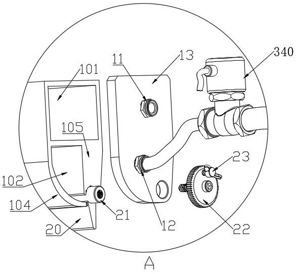
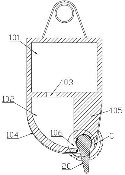
[0039] Such as Figure 2 to Figure 7 As shown, a printed circuit board silk screen scraper assembly includes: a mounting tube 10 and a scraper 20 .

[0040] Specifically, such as image 3 and Figure 4 As shown, the installation tube 10 includes an upper cavity 101 and a lower cavity 102 arranged downwards in a cross-sectional view along the length direction, and both the upper cavity 101 and the lower cavity 102 can be used to store solder resist ink. There are communication holes 103 between the upper cavity 101 and the lower cavity 102 , and a plurality of communication holes 103 are arranged at intervals along the length direction of the installation tube 10 to facilitate the circulation of the solder resist ink. The upper cavity 101 is provided with a feed joint 11 for filling solder resist ink, and the lower cavity 102 is provided with an outlet joint 12, which is in a normally closed state. When working, the outlet joint 12 is closed to prevent the solder resist ink f...

Embodiment 2

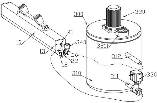
[0049] Such as figure 1 As shown, a printed circuit board solder resist ink filling system includes the printed circuit board silk screen scraper assembly of Embodiment 1 and a feeding device 300 .

[0050] The feeding device 300 includes a storage tank 310. The storage tank 310 is provided with a discharge pipe 311 and a recovery pipe 312. The discharge pipe 311 is provided with a discharge pump 330 to extract the solder resist ink in the storage tank 310. The feed joint 11 Both are connected with the discharge pipe 311, the outlet joint 12 is connected with the recovery pipe 312, and the recovery pipe 312 is provided with a valve 340, and the valve is in a normally closed state.

[0051] Such as figure 1 and Figure 8 As shown, the feeding device 300 also includes an agitator 320, and the agitator 320 includes a cover plate 321 for sealing the storage tank 310. The bottom of the cover plate 321 is provided with a rotating stirring shaft 322, and the bottom is provided with...

specific Embodiment approach

[0054] Specific implementation: when in use, the valve 340 is in a closed state, and the solder resist ink and additives are added into the storage tank 310 from the feeding nozzle 3211, or the mixed solder resist ink is put into the storage tank 310, and the agitator 320 is used to Stir the solder resist ink in the storage tank 310 to prevent the additives in the solder resist ink from sinking to the bottom and maintain the stability of the viscosity of the solder resist ink; The joint 11 is injected into the upper cavity 101 of the installation pipe 10, and the solder resist ink enters the lower cavity 102 from each communication hole in the upper cavity 101, and then is discharged through the discharge port 106, and flows into the net along the side wall of the scraper 20. plate. Because the solder resist ink pumped out by the discharge pump 330 can be injected in a pulse form, so that the flow rate of the solder resist ink fluctuates, the upper cavity 101 can stabilize the...


PUM


Abstract

The application provides a printed circuit board silk screen scraper assembly, including: a mounting tube and a scraper. The installation tube includes an upper cavity and a lower cavity. The upper cavity is provided with a feed joint, and the lower cavity is provided with an outlet joint. The lower section of the installation tube includes a front side wall and a rear side wall, and the front side wall and the rear side wall A discharge port for the solder resist ink is provided between the ends of the scraper, and the discharge port faces the direction opposite to the moving direction of the scraper assembly. Both ends of the installation pipe are provided with end caps. The length of the scraper is the same as the length of the discharge port. The two ends of the scraper are connected to the end caps at both ends. The top of the scraper and the bottom of the rear side wall are rotationally matched, and the distance between the side of the scraper and the end of the front side wall is adjustable. . At the same time, a printed circuit board solder resist ink filling system is provided, which includes the above-mentioned printed circuit board silk screen scraper assembly and a feeding device, and the feeding device includes a material storage tank and a stirrer. The solution of the present application can prevent defective printed circuit boards, avoid damage to the screen board, and improve production efficiency.

Description

technical field [0001] The invention belongs to the field of printed circuit board production and manufacturing, and in particular relates to a printed circuit board silk screen scraper assembly and a solder resist ink filling system. Background technique [0002] The silk screen printing process of printed circuit boards refers to the process of applying a layer of solder resist ink after the wiring diagram of printed circuit boards is completed. At present, most silk screen printing machines are used for silk screen printing. The stencil moves in a straight line, and then the screen printing stencil uses the pre-processed screen printing pattern when the solder resist ink penetrates the screen printing stencil and then adheres to the printed circuit board. [0003] In the prior art, the solder resist ink is usually poured directly on the screen printing screen during silk screen printing, and then scraped with a scraper to achieve the purpose of screen printing, and most o...

Claims


Application Information

Patent Timeline
Patent Type & Authority Patents(China)
IPC IPC(8): B41F15/40B41F15/42B41F15/14
CPCB41F15/14B41F15/40B41F15/42
Inventor 李清华牟玉贵张仁军杨海军邓岚
Owner 四川英创力电子科技股份有限公司
Learn More