
a conveying device

A conveying device and conveying frame technology, which is applied in the direction of conveyors, conveyor objects, transportation and packaging, etc., can solve problems such as labor-intensive, device outage, etc., and achieve the effect of easy installation, convenient assembly, and labor saving

Active Publication Date: 2021-07-27
荣智工企智能技术(昆山)有限公司
View PDF6 Cites 0 Cited by
  • Summary
  • Abstract
  • Description
  • Claims
  • Application Information

AI Technical Summary

Problems solved by technology

[0004] The conveyor rollers on the transmission device need to be equipped with transmission wheels at the end, and a belt needs to be installed between every two transmission wheels, and this form of transmission requires a large number of parts. If one of the belts is loose, the device will be damaged. Out of service, many belts need to be installed during assembly, which will also consume a lot of labor

Method used


Image

  • a conveying device
  • a conveying device
  • a conveying device

Examples


Embodiment Construction

[0031]In order to make the object, technical solution and advantages of the present invention clearer, the present invention will be further described in detail below in conjunction with the accompanying drawings and embodiments. It should be understood that the specific embodiments described here are only used to explain the present invention, not to limit the present invention.

[0032] In describing the present invention, it should be understood that the terms "longitudinal", "transverse", "upper", "lower", "front", "rear", "left", "right", "vertical", The orientations or positional relationships indicated by "horizontal", "top", "bottom", "inner", "outer", etc. are based on the orientations or positional relationships shown in the drawings, and are only for the convenience of describing the present invention, rather than indicating or It should not be construed as limiting the invention by implying that a referenced device or element must have a particular orientation, be ...


PUM


Abstract

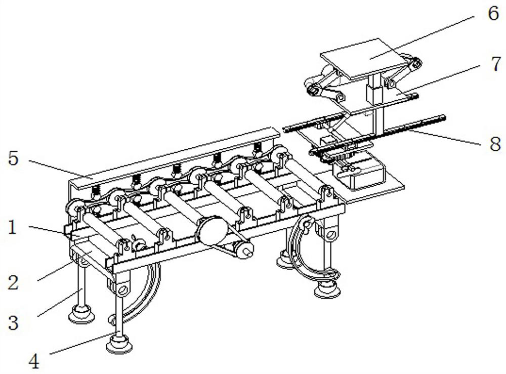
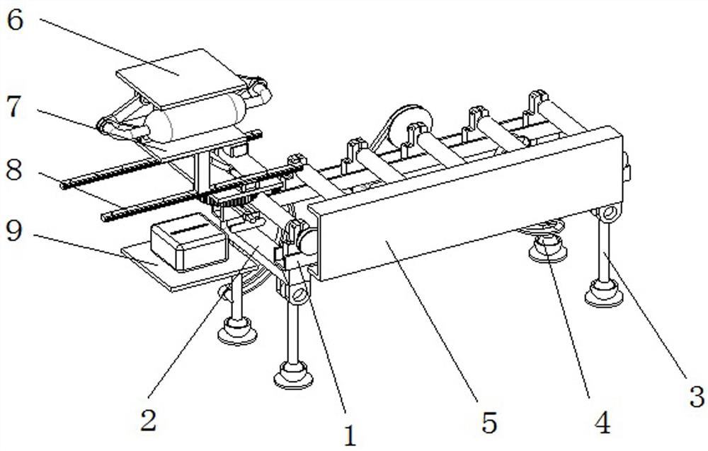
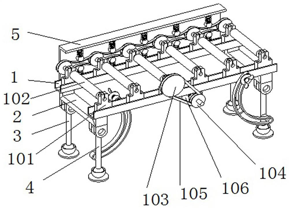
The invention discloses a conveying device, which belongs to the field of conveying devices and comprises a conveying frame. There are two conveying frames in total, and the bottom end of the conveying frame is provided with two connecting frames, and the ends of the two connecting frames are respectively connected to the The bottom surface of the conveying frame is fixedly connected, and the inner side of the conveying frame is fixedly installed with several fixed axle seats, and every two fixed axle seats form a group, and conveying rollers are arranged between each group of fixed axle seats, and the ends of the conveying rollers are arranged There is a round rod interspersed inside the fixed shaft seat, and the end of one of the conveying rollers is fixedly installed with a driving roller, and a reduction wheel is installed on one side of the driving roller. The reduction wheel and the driving roller are connected by a reduction belt, and the reduction wheel The disc is installed on the output end of the geared motor, and the geared motor is fixedly connected with the side wall of the conveying frame, and the bottom end of the conveying frame is provided with two fixed legs and movable legs. The reduction motor of the present invention drives one of the conveying rollers to rotate through the reduction belt.

Description

technical field [0001] The invention relates to the field of conveying equipment, in particular to a conveying device. Background technique [0002] With the development of industrial technology, the modern transportation industry has become more and more perfect. The development of network technology has led to the explosive development of online shopping. The main delivery channel for online shopping is express delivery, and the amount of modern express delivery is huge. Express packaging and Sorting has led to the rapid development of the current express delivery equipment. The existing express delivery equipment is equipped with many conveying rollers, and these conveying rollers need to push the express packaging boxes forward step by step; [0003] Logistics refers to the realization of the planning and implementation of raw materials, semi-finished products, finished products or related information from the origin of the product to the place of consumption of the prod...

Claims


Application Information

Patent Timeline
Patent Type & Authority Patents(China)
IPC IPC(8): B65G13/07B65G13/12B65G47/22B65G47/74
CPCB65G13/07B65G13/12B65G47/22B65G47/74B65G2201/025B65G2201/0285
Inventor 徐海栋范晋夏志军王璞陈海伦陈永昌孙国春周树华孔杰杰蔡琦尤浩嵇筱菁
Owner 荣智工企智能技术(昆山)有限公司
Learn More