Valve lock clamping groove profiling clamping plate

A technology of valve lock clips and clamps, which is applied in the direction of instruments, measuring devices, mechanical measuring devices, etc., can solve the problems affecting product processing quality and production efficiency, affecting the assembly function of valve products, reducing the frequency of product total length inspection, etc., and achieving improvement The effect of self-inspection detection frequency, reduction of use frequency and cost saving

Pending Publication Date: 2021-06-18
江苏沃得机电集团有限公司
View PDF5 Cites 2 Cited by
  • Summary
  • Abstract
  • Description
  • Claims
  • Application Information

AI Technical Summary

Problems solved by technology

[0002] In the production and processing process of the valve, the process of grinding the lock clip groove of the valve is a relatively critical process, and the size of the lock clip groove R and the bottom diameter of the groove will affect the assembly function of the valve product. In the past, the size of the lock clip groove R The detection can only be carried out by the high-precision universal mirror in the laboratory, and the laboratory detects a large number of product types and quantities in the daily production process, and often needs to wait when the product is sent to the inspection of the total length, or reduce the total length of the product. The frequency of inspection will easily lead to a greater risk in the production process, that is, the total length of the product is out of tolerance in batches
No matter which method is used, it will greatly affect the product processing quality and production efficiency.

Method used


Image

  • Valve lock clamping groove profiling clamping plate
  • Valve lock clamping groove profiling clamping plate

Examples


Embodiment Construction

[0018] In order to deepen the understanding of the present invention, the present invention will be further described below in conjunction with the embodiments and accompanying drawings. The embodiments are only used to explain the present invention and do not constitute a limitation to the protection scope of the present invention.

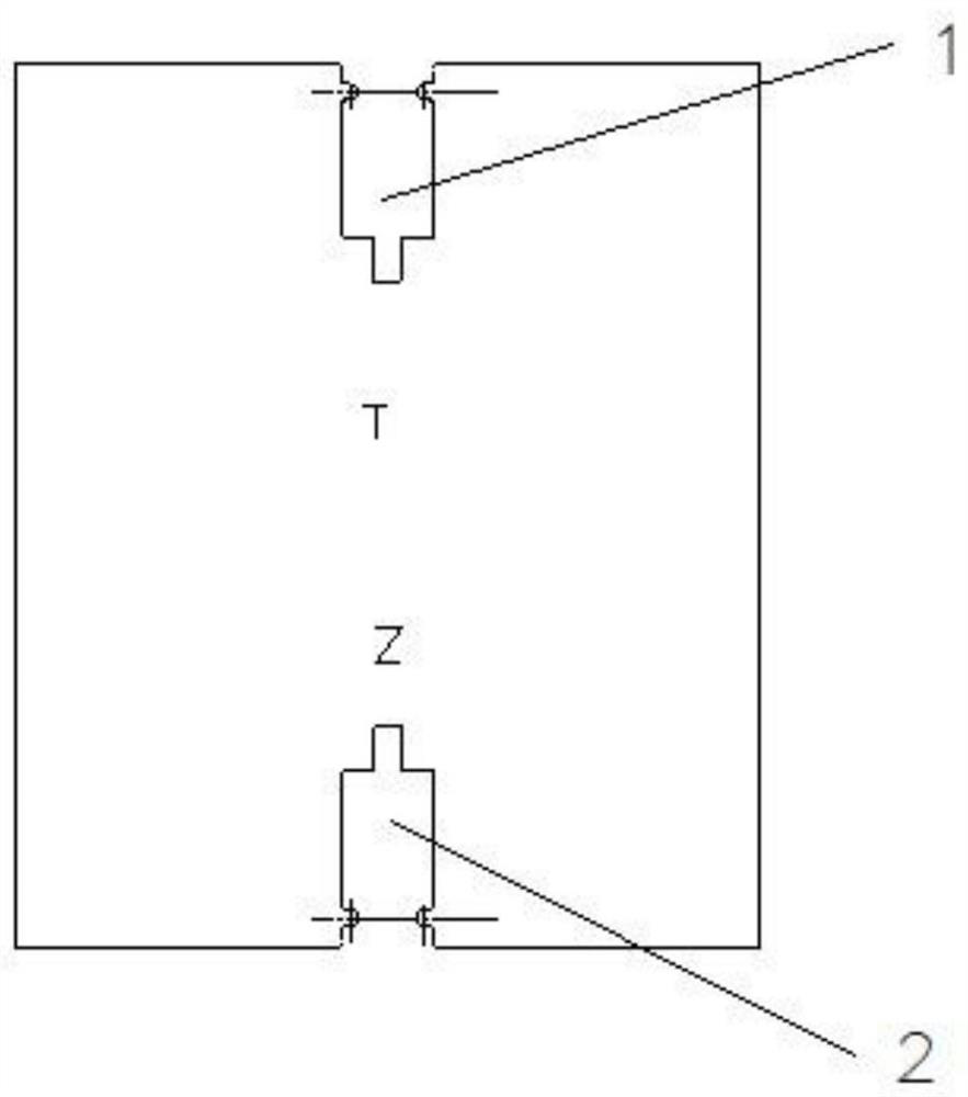
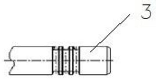
[0019] Such as Figure 1~2 As shown, the valve lock clamp groove profiling clamping plate includes a through gauge 1, a stop gauge 2, and a detected workpiece 3.

[0020] The valve lock clamping groove profiling clamp includes a clamp main body, one end of the clamp main body is provided with a stop gauge 2, and the other end of the clamp main body is provided with a through gauge 1, and the shape of the stop gauge 2 is a rectangular groove. Both sides of the notch of the stop gauge 2 are provided with a semicircular protrusion, and the distance between the protrusions on both sides of the notch of the stop gauge 2 is equal to the lower limit of ...


PUM


Abstract

The invention discloses a valve lock clamping groove profiling clamping plate, which comprises a clamping plate body, a no-go gauge is arranged at one end of the clamping plate body, a go gauge is arranged at the other end of the clamping plate body, the no-go gauge is a rectangular groove, the two sides of a notch of the no-go gauge are each provided with a semicircular protrusion, and the go gauge is in the shape of a rectangular groove. The two sides of the go gauge notch are respectively provided with a semicircular protrusion. The novel profiling clamping plate for the valve collet groove is convenient to use and can be used by training common operators slightly without professional training guidance; the clamping plate is placed on a testing fixture table beside production equipment, so that the size of a product lock clamping groove can be measured at any time, and convenience and rapidness are achieved. The detection efficiency is improved, the production efficiency is also improved, the self-inspection detection frequency of an operator can be improved, and the risk of batch rejection in the machining process can be prevented. By using the novel valve collet groove profiling clamp, the use frequency of a high-precision instrument universal mirror in a laboratory can be reduced, and the cost is saved to a certain extent.

Description

technical field [0001] The invention relates to a profiling clamping plate for an air door lock clamping groove. Background technique [0002] In the production and processing process of the valve, the process of grinding the lock clip groove of the valve is a relatively critical process, and the size of the lock clip groove R and the bottom diameter of the groove will affect the assembly function of the valve product. In the past, the size of the lock clip groove R The detection can only be carried out by the high-precision universal mirror in the laboratory, and the laboratory detects a large number of product types and quantities in the daily production process, and often needs to wait when the product is sent to the inspection of the total length, or reduce the total length of the product. The frequency of inspection will easily lead to a greater risk in the production process, that is, the total length of the product is out of tolerance in batches. No matter which meth...

Claims


Application Information

Patent Timeline
Patent Type & Authority Applications(China)
IPC IPC(8): G01B5/00
CPCG01B5/00
Inventor 张涛
Owner 江苏沃得机电集团有限公司
Why Eureka
Try Eureka