Device and method for reducing electromagnetic interference of dc-dc power supply
A DC-DC, electromagnetic interference technology, applied in output power conversion devices, electrical components, conversion equipment without intermediate conversion to AC, etc., can solve problems such as electromagnetic interference, instrument equipment failure, interference, etc., to facilitate charging current The effect of size adjustment, electromagnetic interference amplitude reduction, and sub-harmonic component reduction
- Summary
- Abstract
- Description
- Claims
- Application Information
AI Technical Summary
Problems solved by technology
Method used
Image
Examples
Embodiment 1
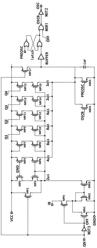
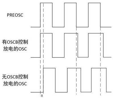
[0051] This embodiment discloses a device for reducing electromagnetic interference of a DC-DC power supply, including: a driving circuit, a first current mirror, a second current mirror, a counter and a latch. The drive circuit is controlled to generate a drive current. In some embodiments, the driving circuit generates a driving current when the first enabling signal QN is an on signal, and does not generate a driving current when the first enabling signal QN is an off signal. The first current mirror and the second current mirror respectively mirror the driving current of the driving circuit to charge the first capacitors respectively. The output terminal of the latch obtains the inversion signal OSCB through the first inverter, and the counter counts the pulses of the inversion signal OSCB cyclically to generate several records, and controls the second current mirror to charge the first capacitor according to the counting speed In this way, the first current mirror acts a...
Embodiment 2
[0061] This embodiment discloses a device for reducing electromagnetic interference of a DC-DC power supply, comprising: a drive circuit, a first current mirror, a second current mirror, a counter and a latch.
[0062] Such as figure 1 As shown, the drive circuit includes a first P-type field effect transistor MP1, a second P-type field effect transistor MP2, a third P-type field effect transistor MP3, a fourth P-type field effect transistor MP4, a first N-type field effect transistor MN1 , the second N-type field effect transistor MN2 and the third N-type field effect transistor MN3. The source of the second P-type field effect transistor MP2 is connected to the power supply VCC, the gate is grounded, and the drain is connected to the source of the third P-type field effect transistor MP3. The gate of the third P-type field effect transistor MP3 is connected to the drain, and the drain is connected to the drain of the third N-type field effect transistor MN3. The source of...
Embodiment 3
[0073] This embodiment discloses a method for reducing electromagnetic interference of a DC-DC power supply, including:
[0074] A. Generate drive current.
[0075] By pulling down the potential at one end of the impedance element, a potential difference is generated at both ends of the impedance element, and a driving current is generated on the impedance element.
[0076] The behavior of the pull-down potential can be realized by designing the pull-down current circuit. The pull-down current circuit can be turned on or off by the first enable signal. Such as figure 1 As shown, in one embodiment, the fourth P-type field effect transistor MP4, the first N-type field effect transistor MN1, the second N-type field effect transistor MN2, and the third N-type field effect transistor MN3 constitute a pull-down current circuit. The sources of the four P-type field effect transistors MP4 are connected to the second enabling signal IB, the gates are connected to the gate of the fi...
PUM
 Abstract
Description
Claims
Application Information
 - R&D
- Intellectual Property
- Life Sciences
- Materials
- Tech Scout
- Unparalleled Data Quality
- Higher Quality Content
- 60% Fewer Hallucinations
Browse by: Latest US Patents, China's latest patents, Technical Efficacy Thesaurus, Application Domain, Technology Topic, Popular Technical Reports.
© 2025 PatSnap. All rights reserved.Legal|Privacy policy|Modern Slavery Act Transparency Statement|Sitemap|About US| Contact US: help@patsnap.com


