Unlock instant, AI-driven research and patent intelligence for your innovation.

Improvement method of LC filter bridge type uncontrolled rectification circuit

A rectifier circuit and bridge technology, applied in the field of bridge uncontrolled rectification, can solve the problem of increasing the reactive power component of the circuit, and achieve the effect of suppressing distortion and loss of duty cycle, widely used, and expanding the load range.

Active Publication Date: 2021-06-18
HARBIN INST OF TECH
View PDF5 Cites 0 Cited by
  • Summary
  • Abstract
  • Description
  • Claims
  • Application Information

AI Technical Summary

Problems solved by technology

[0005] Aiming at the problem that the input impedance of the existing LC filter bridge rectifier circuit is obviously capacitive and the reactive component of the circuit increases when the load is small, the present invention provides an improvement method for the LC filter bridge rectifier circuit without control

Method used


Image

  • Improvement method of LC filter bridge type uncontrolled rectification circuit
  • Improvement method of LC filter bridge type uncontrolled rectification circuit
  • Improvement method of LC filter bridge type uncontrolled rectification circuit

Examples


specific Embodiment approach 1

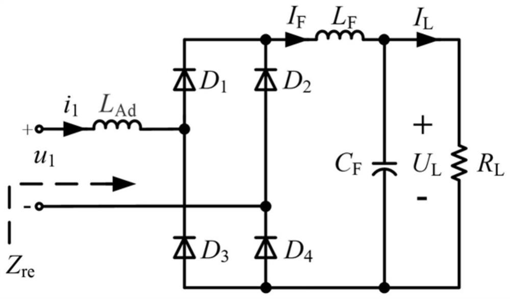
[0030] Specific implementation mode 1. Combination Figure 1 to Figure 3 As shown, the present invention provides an improved method for an LC filter bridge type uncontrolled rectifier circuit, based on the traditional LC filter bridge type uncontrolled rectifier circuit, an input terminal of the traditional LC filter bridge type uncontrolled rectifier circuit is connected in series to assist Inductance L Ad , the improved LC filter bridge uncontrolled rectification circuit is obtained;

[0031] The auxiliary inductance L Ad When the load resistance is too small and the rectifier circuit works in discontinuous conduction mode, the input current will not change abruptly, but there is a commutation process; at the same time, the input voltage is not equal to zero.

[0032] figure 1 In this case, an auxiliary inductance L with a small inductance is connected in series with the input side of the traditional LC filter bridge rectifier circuit Ad . Among them, u 1 and i 1 Res...

specific Embodiment

[0052] Specific examples: combining Figure 10 to Figure 15 As shown, the constant voltage output S / SP compensation topology is a commonly used compensation topology in IPT systems, which has a constant output voltage independent of the load and strong anti-offset capability. In order to verify the effectiveness of the improved rectifier circuit of the present invention, an IPT system based on constant voltage S / SP compensation is designed. The performance of the improved LC filter bridge uncontrolled rectifier circuit is verified by comparing the performance of the improved LC filter bridge uncontrolled rectifier circuit system with the traditional LC filter bridge rectifier system. The schematic diagram of the S / SP compensation topology circuit using the improved LC filter bridge uncontrolled rectification circuit is as follows: Figure 4 as shown, Figure 10 It is a schematic diagram of a S / SP compensation topology circuit using a traditional rectifier. In the improved r...


PUM


Abstract

The invention discloses an improvement method of an LC filter bridge type uncontrolled rectification circuit, and belongs to the technical field of bridge type uncontrolled rectification. The invention aims to solve the problems that the input impedance is obviously capacitive and the reactive component of the circuit is increased when the load of the existing LC filter bridge rectification circuit is small. According to the method, based on a traditional LC filter bridge type uncontrolled rectification circuit, one input end of the traditional LC filter bridge type uncontrolled rectification circuit is connected with an auxiliary inductor LAD in series, and an improved LC filter bridge type uncontrolled rectification circuit is obtained; when the load resistance value is too small and the rectification circuit works in an interrupted conduction mode, the auxiliary inductor LAd enables the input current not to suddenly change, and a current conversion process exists; and meanwhile, the input voltage is not equal to zero. The system transmission efficiency can be improved.

Description

technical field [0001] The invention relates to an improvement method of an LC filter bridge type uncontrolled rectification circuit, and belongs to the technical field of bridge type uncontrolled rectification. Background technique [0002] The bridge uncontrolled rectifier circuit is widely used in the field of power electronic converters due to its simple structure, no need for control and high stability. [0003] The bridge rectifier circuit is a full-wave rectifier, the output contains DC components and high-order harmonic components, and it is often necessary to connect a low-pass filter after it to filter out the harmonic components. Commonly used uncontrolled rectifier filter structures are divided into C filter bridge rectifier and LC filter bridge rectifier, and different rectification and filter structures need to be used in conjunction with different circuit structures. For example, in inductive wireless power transfer technology, different compensation topologi...

Claims


Application Information

Patent Timeline
Patent Type & Authority Applications(China)
IPC IPC(8): H02M3/08H02M1/12
CPCH02M3/08H02M1/12
Inventor 王懿杰麦建伟曾宪瑞姚友素张相军徐殿国
Owner HARBIN INST OF TECH