Communication device insulation processing system

A technology for insulation treatment and communication devices, which is applied in coatings, devices for coating liquid on the surface, etc., and can solve problems such as the inability to adhere to electronic components

Active Publication Date: 2021-06-22
HUAIHUA JIANNAN ELECTRONICS TECH
View PDF5 Cites 0 Cited by
  • Summary
  • Abstract
  • Description
  • Claims
  • Application Information

AI Technical Summary

Problems solved by technology

But this device can't make the electronic components fully adhere to the insulating oil

Method used


Image

  • Communication device insulation processing system
  • Communication device insulation processing system
  • Communication device insulation processing system

Examples


specific Embodiment approach 1

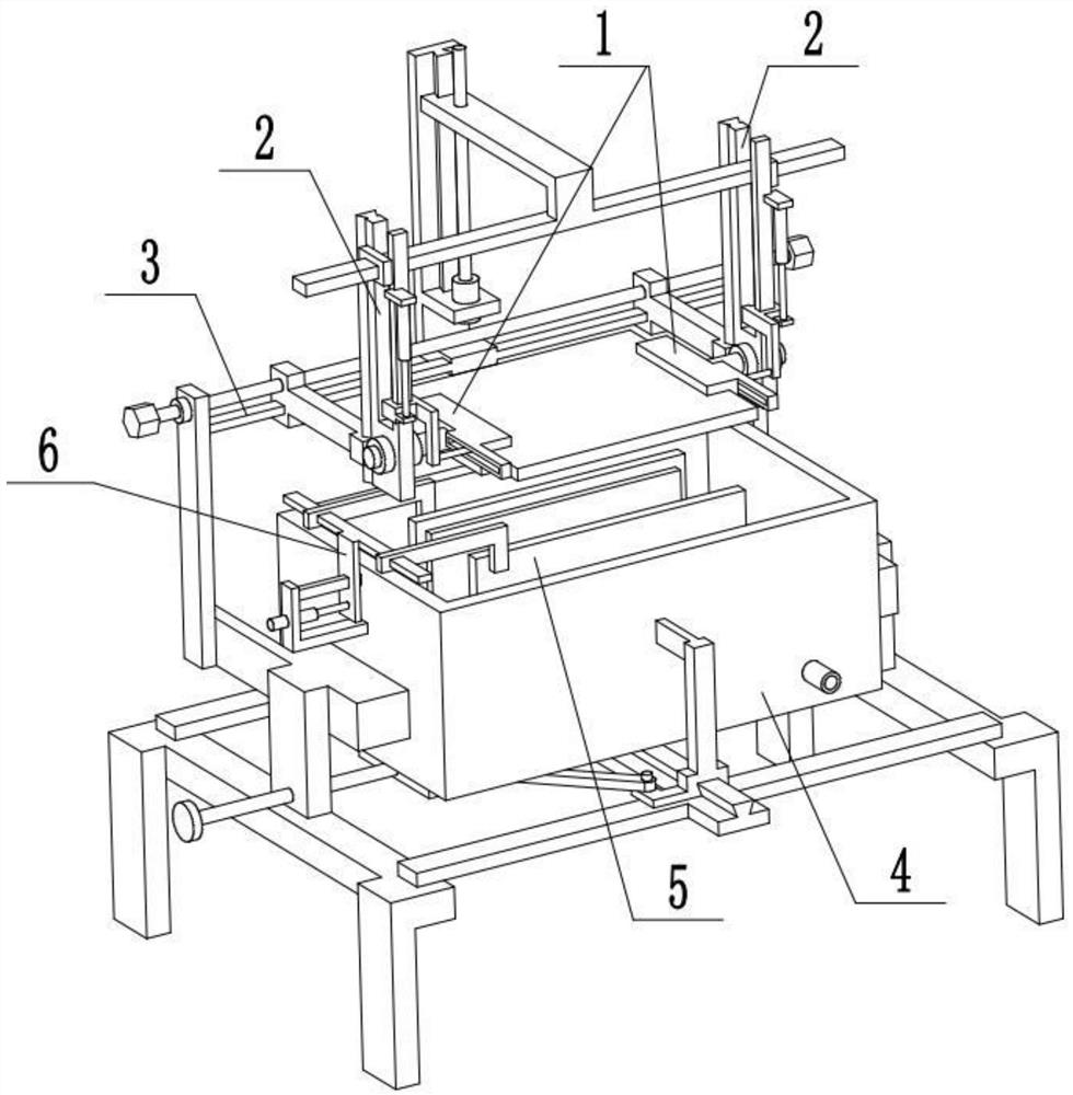
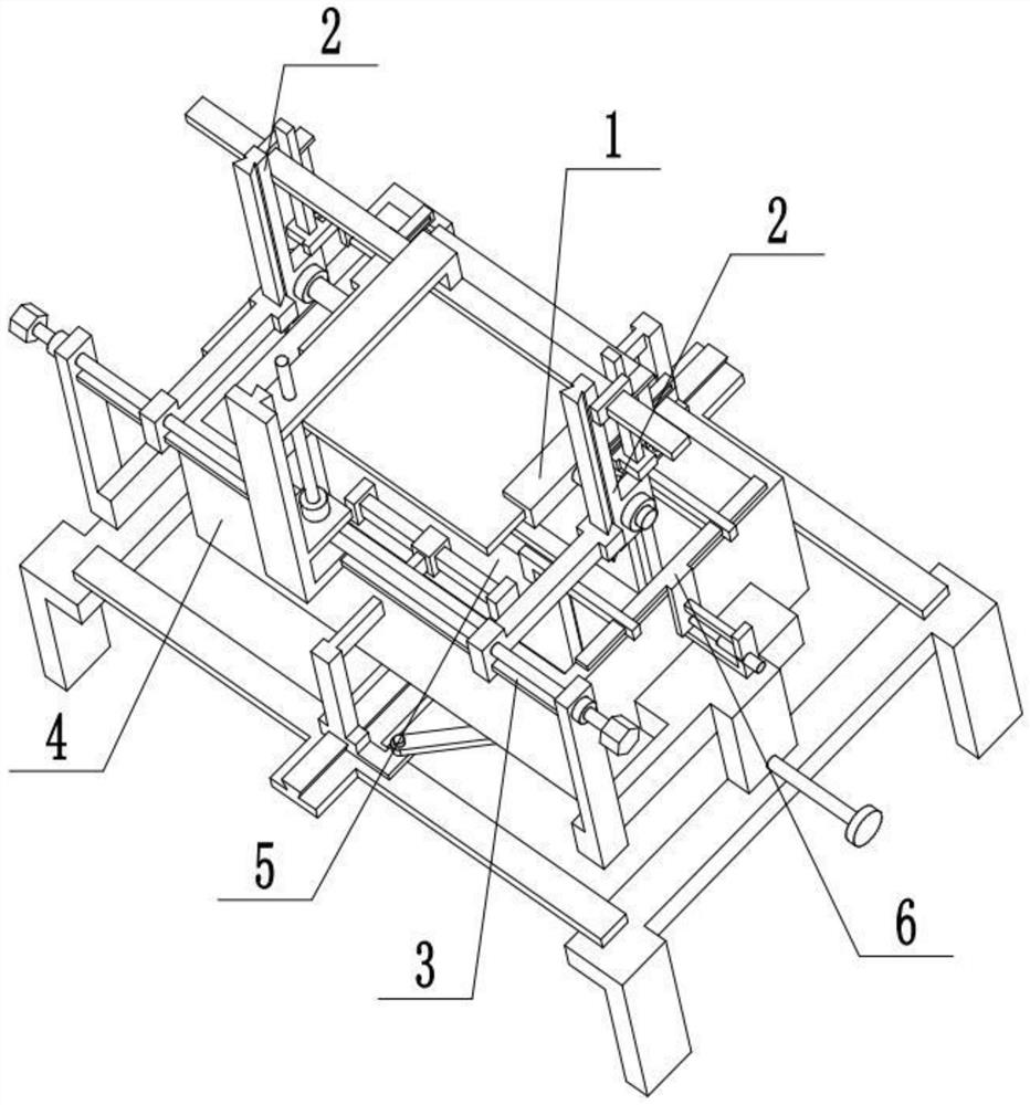
[0025] Combine below Figure 1-7 Describe this embodiment, an insulation treatment system for communication devices, including a chassis 3-8, an oil tank 4, a brush plate 5, an L-shaped rod 5-1, a trapezoidal edge 5-2, an I-shaped frame 5-3, and an articulated arm 5-4, the square plate 5-5 and the externally threaded rod 5-6, the fuel tank 4 is fixedly connected between the two underframes 3-8, and the two L-shaped rods 5-1 are symmetrically slidably connected to the bottom of the fuel tank 4 At the front and rear ends, the inner ends of the two L-shaped rods 5-1 are respectively provided with a brush plate 5, and the outer ends of the two L-shaped rods 5-1 are respectively slidably connected to the two ends of the trapezoidal rib 3 5-2, and the trapezoidal rib Three 5-2 are fixedly connected to the middle part of the I-shaped frame 5-3, the I-shaped frame 5-3 is fixedly connected on the two underframes 3-8, and the external threaded rod 5-6 is threadedly connected to the left...

specific Embodiment approach 2

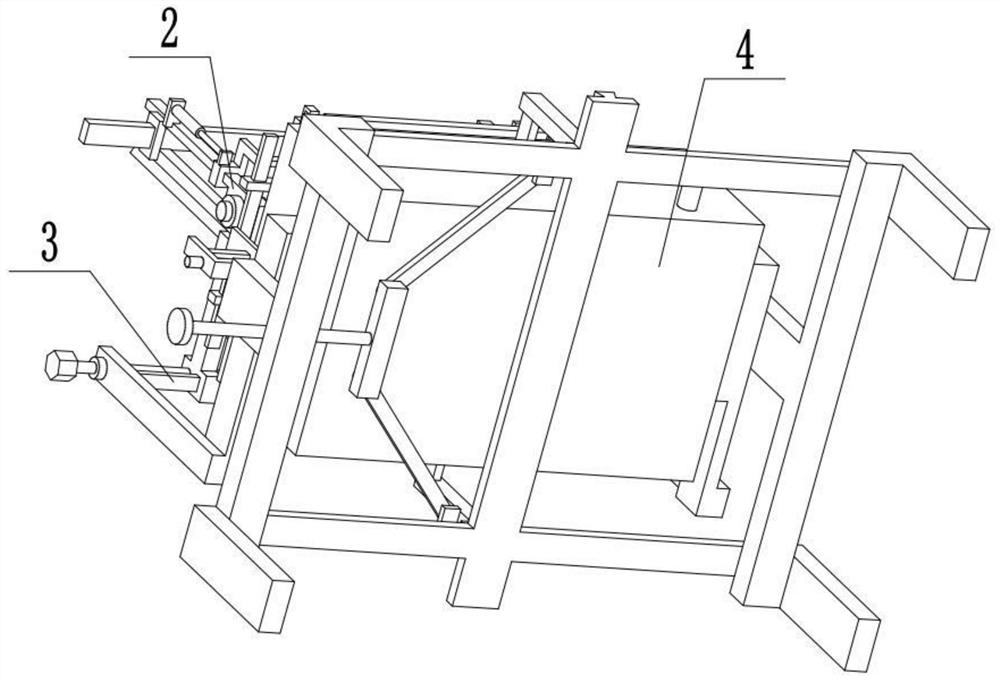
[0027] Combine below Figure 1-7 To illustrate this embodiment, the communication device insulation treatment system further includes a square rod 5-7, an ear plate 5-8, a lower T-shaped plate 6, an insertion rod 6-1, an L-shaped plate 6-2 and a cylinder two 6-3, the outer end surfaces of the two brush plates 5 are respectively fixedly connected with a square rod 5-7, and the inner ends of the two L-shaped rods 5-1 are respectively movably connected with a square rod 5-7; the L-shaped board 6- 2 is fixedly connected to the left end of the fuel tank 4, the plunger 6-1 and the second oil cylinder 6-3 are fixedly connected to the L-shaped plate 6-2, and the telescopic end of the second oil cylinder 6-3 is fixedly connected to the lower end of the lower T-shaped plate 6, The lower T-shaped plate 6 is slidably connected to the insertion rod 6-1, and the two ends of the lower T-shaped plate 6 are respectively movably connected to an ear plate 5-8, and the two ear plates 5-8 are resp...

specific Embodiment approach 3

[0029] Combine below Figure 1-7To illustrate this embodiment, the communication device insulation treatment system further includes a U-shaped splint 1, an upper T-shaped plate 1-1, a guide rod 3, a shaft frame 3-1, a rear frame plate 3-2, and a trapezoidal edge 2 3-3. Motor 3-4 and lead screw 3-5; two base frames 3-8 are respectively fixedly connected with a shaft frame 3-1, and the guide rod 3 is fixedly connected between the two shaft frames 3-1, and the rear frame The plate 3-2 is fixedly connected to the middle part of the guide rod 3, the trapezoidal edge 2 3-3 and the motor 3-4 are all fixedly connected to the rear frame plate 3-2, and the output shaft of the motor 3-4 is fixedly connected to the lead screw 3-5, The upper T-shaped plate 1-1 is slidingly connected on the trapezoidal edge 2 3-3, the upper T-shaped plate 1-1 is threadedly connected with the lead screw 3-5, and a U-shaped splint 1 is respectively provided at both ends of the lead screw 3-5 . Insert the c...


PUM


Abstract

The invention discloses a communication device insulation processing system, and relates to the technical field of power electronic devices. The communication device insulation processing system comprises bottom frames, an oil tank, a brush plate, L-shaped rods, a third trapezoidal edge, an I-shaped frame, a hinge arm, a square plate and an external threaded rod. The communication device insulation processing system has the beneficial technical effect that electronic components can be fully adhered with insulation oil. The oil tank is fixedly connected between the two bottom frames, the two L-shaped rods are symmetrically connected to the front end and the rear end of the oil tank in a sliding mode, the inner ends of the two L-shaped rods are each provided with one brush plate, the outer ends of the two L-shaped rods are connected to the two ends of the third trapezoidal edge in a sliding mode, the third trapezoidal edge is fixedly connected to the middle of the I-shaped frame, and the I-shaped frame is fixedly connected to the two bottom frames. The external threaded rod is in threaded connection to the bottom frame at the left end, the right end of the external threaded rod is rotationally connected with a square plate, the square plate is rotationally connected with two hinge arms, and the two hinge arms are rotationally connected to the lower ends of the L-shaped rods respectively.

Description

technical field [0001] The invention relates to the technical field of power electronic devices, in particular to an insulation treatment system for communication devices. Background technique [0002] The patent number is CN201520994278.5, an environment-friendly oil insulation treatment system for power electronic components. The utility model relates to an environment-friendly oil insulation treatment system for power electronic components, which includes an oil supply chamber, an oil inlet pipe is connected to the upper part of the right side of the oil supply chamber, an oil stirring and dilution treatment chamber is connected to the lower part of the oil supply chamber, and an oil stirring and dilution treatment chamber is connected to the oil supply chamber. The middle part of the lower part is connected with an oil outlet pipe, the left and right liquid supply pipes are respectively connected to the left and right sides of the upper part of the oil stirring and dilut...

Claims


Application Information

Patent Timeline
IPC IPC(8): B05C3/09B05C13/02
CPCB05C3/09B05C13/02
Inventor 邹杰海
Owner HUAIHUA JIANNAN ELECTRONICS TECH
Why Eureka
Try Eureka