Feed shaft diagnostic device and feed shaft diagnostic method for machine tool

A diagnostic device and feed shaft technology, which is applied in the direction of metal processing machinery parts, machine gear/transmission mechanism testing, metal processing equipment, etc., can solve the problems of sensor interference, increased sensor cost, increased failure risk, etc., and achieve high precision Effect

Pending Publication Date: 2021-06-22
OKUMA CORP
View PDF3 Cites 0 Cited by
  • Summary
  • Abstract
  • Description
  • Claims
  • Application Information

AI Technical Summary

Problems solved by technology

That is, in the above-mentioned method, there are problems in that the cost of the sensor itself increases, the manufacturing cost increases due to the wiring work performed on the information collecting device, and the risk of failure due to the failure of the sensor itself increases.
In addition, loads, vibrations, and changes in the weight of workpieces that occur during workpiece processing can interfere with sensor output, and therefore there is a problem that a special operation for diagnosis is required that is different from normal operation.

Method used


Image

  • Feed shaft diagnostic device and feed shaft diagnostic method for machine tool
  • Feed shaft diagnostic device and feed shaft diagnostic method for machine tool
  • Feed shaft diagnostic device and feed shaft diagnostic method for machine tool

Examples


Embodiment Construction

[0025] Embodiments of the present invention will be described below with reference to the drawings.

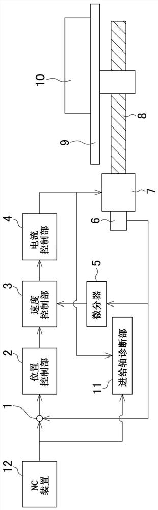
[0026] figure 1 It is an explanatory diagram showing the diagnosis device of the feed shaft according to the present invention.

[0027] In this machine tool, a moving body 9 is provided so as to be slidable by a ball screw 8 which is driven to rotate by a servo motor 7 . The moving body 9 can move linearly along the guide surface of the rolling guide mechanism 10 .

[0028] In machining of a workpiece not shown, the servomotor 7 drives the movable body 9 via the ball screw 8 to move the workpiece placed on the movable body 9 to a predetermined position, thereby performing machining.

[0029] The feed axis diagnosis device includes: a position detector 6, which is provided on the servo motor 7, and detects the position of the moving body 9 by detecting the rotational position of the servo motor 7; an NC device 12, which outputs a position command value of the moving body 9 ...


PUM


Abstract

The invention provides a feed shaft diagnostic device and a feed shaft diagnostic method for a machine tool. On the basis of a control signal used in a feed shaft of a normal machine tool, abnormality detection of a rolling guide mechanism in consideration of the influence of a weight change of a workpiece can be performed. The feed axis diagnostic device is provided with a feed axis diagnostic unit (11) that detects an abnormality in a rolling guide mechanism (10) in a machine tool that machines a workpiece while driving a moving body (9) along a guide surface of the rolling guide mechanism (10) by means of a ball screw (8). A feed shaft diagnosis unit (11) acquires a feed speed during non-machining and a load applied to a ball screw (8) at the feed speed, and detects an abnormality on the basis of an approximation function calculated on the basis of the relationship between a plurality of feed speeds acquired under a plurality of different feed speed conditions within a predetermined period and the load.

Description

technical field [0001] The present invention relates to a feed axis diagnosis device and a feed axis diagnosis method of a machine tool having a feed axis that drives a moving body along a rolling guide mechanism. Background technique [0002] In the feed axes of machine tools in recent years, a system in which a moving body is driven by transmitting a rotational motion of a motor to a ball screw to enable movement along a rolling guide mechanism has been widely adopted. However, if the drive components such as the ball screw or the rolling guide mechanism deteriorate over time, foreign matter enters, or the lubrication is poor, the feed shaft will not operate normally, and the shape of the workpiece or the shape of the machined surface will be defective. Poor processing such as bad will have a bad impact on production. Therefore, in order to achieve stable production during the operation of machine tools, it is desired to detect machine abnormalities, notify managers and o...

Claims


Application Information

Patent Timeline
Patent Type & Authority Applications(China)
IPC IPC(8): B23Q17/00B23Q17/10
CPCB23Q17/00B23Q17/10G01M13/02
Inventor 北乡匠
Owner OKUMA CORP
Why Eureka
Try Eureka