Turbine flange butterfly valve

A flange and butterfly valve technology, which is applied in the field of butterfly valve installation, can solve the problems of low adaptability of the clamping mechanism to the size of the valve body, easy deviation of the valve body from the vertical direction, and low stability of the valve body, so as to expand the applicable scope of clamping , avoid the effect of decreasing the sealing degree and improving the stability

Active Publication Date: 2021-06-22
兹戈图水工业(天津)有限公司
View PDF12 Cites 1 Cited by
  • Summary
  • Abstract
  • Description
  • Claims
  • Application Information

AI Technical Summary

Problems solved by technology

[0003] 1. Because the clamping structure is too simple or the clamping range of the clamping structure is small, the overall stability of the valve body is low, and the valve body is prone to shaking. At the same time, the adaptability of the clamping mechanism to changes in the size of the valve body lower;
[0004] 2. The valve body in the clamped state is easier to deviate from the vertical direction, that is, the valve body is in an inclined state, and the inclined state is more likely to lead to the firmness of the connection between the valve body and the connecting structure, which in turn affects the overall sealing degree

Method used


Image

  • Turbine flange butterfly valve
  • Turbine flange butterfly valve
  • Turbine flange butterfly valve

Examples


Embodiment Construction

[0032] The embodiments of the present invention will be described in detail below with reference to the accompanying drawings, but the present invention can be implemented in many different ways as defined and covered by the claims.

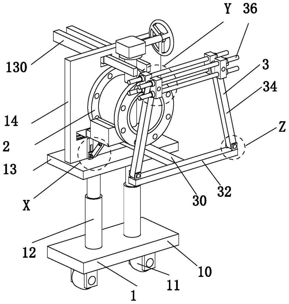
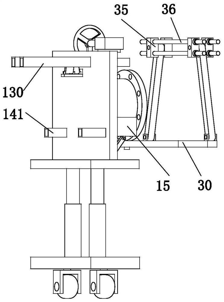
[0033] like Figure 1 to Figure 11 As shown, a turbine flange butterfly valve includes a main solid mechanism 1, a valve body 2 and an auxiliary solid mechanism 3. The lower end of the main solid mechanism 1 is connected to the existing ground by a sliding fit. The main solid mechanism 1 The upper end of the valve body 2 is connected with the valve body 2, and the front end of the valve body 2 is provided with an auxiliary fixing mechanism 3.

[0034]The main solid mechanism 1 includes a base plate 10, a universal wheel 11, an electric push rod 12, a base plate 13, a riser 14 and a support block 15, the lower end of the base plate 10 is symmetrically equipped with a universal wheel 11, and the upper end surface of the base plate 10 Electric push...


PUM


Abstract

The invention relates to a turbine flange butterfly valve. The turbine flange butterfly valve comprises a main fixing mechanism, a valve body and an auxiliary fixing mechanism, wherein the lower end of the main fixing mechanism is connected with existing ground in a sliding fit manner, the upper end of the main fixing mechanism is connected with the valve body, and the auxiliary fixing mechanism is arranged at the front end of the valve body. The turbine flange butterfly valve is installed by adopting multi-clamping design concept, the main fixing mechanism and the auxiliary fixing mechanism are arranged in a combined and separated manner so that the occupied time of the main fixing mechanism and the auxiliary fixing mechanism in the installation process of the single valve body can be shortened, the interval time between continuous installation of the valve body can be shortened, and therefore the overall working efficiency is improved; and meanwhile, the auxiliary fixing mechanism can adapt to the change of the size of a connecting structure, so that the overall clamping application range of the device is expanded.

Description

technical field [0001] The invention relates to the field of butterfly valve installation, in particular to a turbine flange butterfly valve. Background technique [0002] Butterfly valve refers to a valve whose closing part (disc or butterfly plate) is a disc, which rotates around the valve shaft to open and close. It mainly plays the role of cutting and throttling on the pipeline. Flap flap valve) is a regulating valve with simple structure, and it can also be used for switch control of low-pressure pipeline medium. Turbine flange butterfly valve generally adopts three-eccentric multi-layer metal hard seal structure, which is suitable for generators, gas, natural gas, It is used to regulate and cut off the flow of medium on pipelines conveying various corrosive and non-corrosive fluid media in engineering systems such as liquefied petroleum gas, city gas, cold and hot air, chemical smelting, power generation and environmental protection, etc., but in the installation proce...

Claims


Application Information

Patent Timeline
Patent Type & Authority Applications(China)
IPC IPC(8): B25B27/24B25B11/02
CPCB25B27/24B25B11/02
Inventor 周圳慧朱轶静
Owner 兹戈图水工业(天津)有限公司
Why Eureka
Try Eureka