
Cast-in-place pile construction method suitable for drilling and bottom expanding device

A construction method and cast-in-place pile technology, which are applied to sheet pile walls, infrastructure engineering, construction, etc., can solve the problems of large stirring resistance, increased drilling resistance, and inability to promote, and achieve high bending and torsional strength, improved The effect of vertical bearing capacity

Pending Publication Date: 2021-06-22
曹兴明
View PDF1 Cites 0 Cited by
  • Summary
  • Abstract
  • Description
  • Claims
  • Application Information

AI Technical Summary

Problems solved by technology

Summarize the shortcomings of the existing bored grouting bottom expansion piles on the market: a construction method patent name for cast-in-situ piles: it is a borehole pressure grouting superfluid concrete grouting bottom expansion pile and device, patent number: 2005100103564. The main disadvantages of the construction practice summary are as follows: the formation of the mechanical expansion of the device is to rely on the radial extension of the drill bit to the outer side and the rotation to form a circular expansion head, and the expanded soil and cement slurry are mixed to form a cement-soil expansion head
The reasons why the diameter of this device does not meet the design requirements are as follows: the first is that the drill bit is pulled upwards with a steel wire (traction) and the pile end soil cannot be mixed with the cement slurry due to insufficient pulling force.
Second, one side of the drill bit is stretched to scrape the soil, resulting in too much eccentric resistance, and the drill bit is often scraped off to affect the construction.
The third is that when the tension is too large, the pile diameter exceeds the design diameter when the drill pipe is bent and rotated under eccentric force.
Fourth, the single-sided tension and concrete mixing resistance are greater, so that the hinge at the root of the drill bit is deformed and a single wire rope is broken and construction cannot be carried out.
There are structural defects in this device, so it has not been promoted
[0003] There is also a bottom-expanding pile type "construction method and construction device for concrete pouring pile expansion bottom mixing composite foundation" application number: 200410043947.7 The main disadvantage of this method is that its device design has serious defects so that this method cannot be realized. The first is the hydraulic cylinder The disadvantage of installing on both sides of the drill bit is that it occupies the space for the drill bit to return to the soil, and the increase of drilling resistance seriously affects the drilling speed.
The second is that the hydraulic oil cylinder and hydraulic oil pipe on the drill bit are easily damaged by friction in the harsh environment of the underground soil layer, and cannot work normally
The third is that the wide knife protrudes outwards and does not meet the mechanical strength requirements, and is often deformed and damaged, which affects the quality of the expanding head
Fourth, due to the unreliability of the device, the construction method cannot fully realize the design size of the bottom expansion and mixing, so that the process cannot be promoted.

Method used


Image

  • Cast-in-place pile construction method suitable for drilling and bottom expanding device
  • Cast-in-place pile construction method suitable for drilling and bottom expanding device
  • Cast-in-place pile construction method suitable for drilling and bottom expanding device

Examples


Embodiment 2

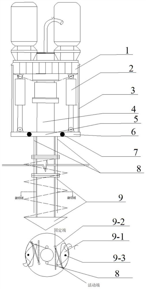
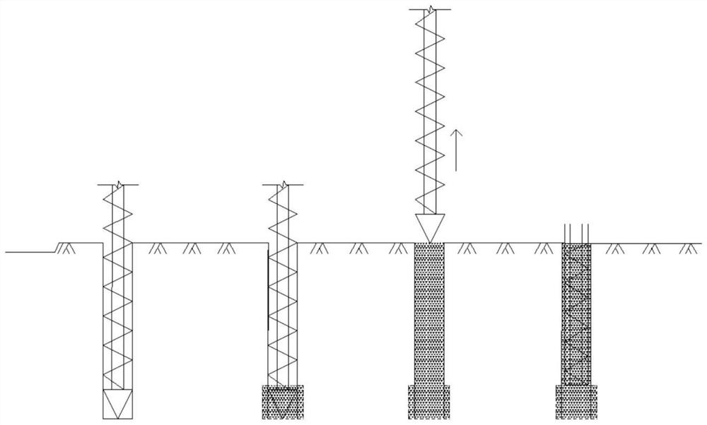
[0033] Example 2: Bottom-expanding pile with superfluid concrete for drilling and pressure grouting. The flow process when the method uses the example 1 drilling bottom expansion device is: when the borehole pressure grouting superfluid concrete pile is drilled into the design elevation, the drilling pressure grouting superfluid concrete (or cement slurry) is fed by the two ends of the power head lower end The side hydraulic cylinder pulls the mechanical turntable to drive the steel wire rope. The lower end of the steel wire rope is connected to the blade of the drill bit and the upper expansion cutter is stretched outward. While rotating and lifting the drill, the bottom is expanded, and the sand at the end of the expanded pile is mixed with superfluid concrete (or cement slurry). After forming the enlarged end, lift the drill and continue to press pour the superfluid concrete to place the reinforcement cage to form a drill hole press pour superfluid concrete bottom expansion ...

Embodiment 3

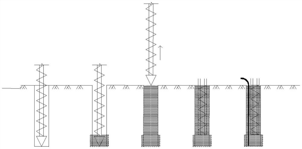
[0035]Example 3: Grouting piles after borehole pressure grouting and superfluid concrete bottom expansion. After the process of using the example 1 drilling bottom expansion device and the embodiment 2 drilling pressure pouring superfluid concrete bottom expansion pile in this method is completed, insert the grouting pipe immediately, clear the water in 6 hours, and inject it after two days The grouting pile is formed by grouting the cement slurry into the superfluid concrete with borehole pressure grouting and expanding the bottom.

[0036] see attached image 3 : Process flow chart of grouting pile after drilling and grouting;

Embodiment 4

[0037] Embodiment 4: Construction method of bored and bottom-expanded cast-in-situ piles in dry operation. When this method uses the drilling bottom expansion device of Example 1, the flow process is: when the drilling rig drills to the pile end design elevation, inject cement slurry and start the bottom expansion device, and lift the drill while stirring while grouting to expand the bottom and lift the drill Finally, the reinforcement cage is placed, and then the concrete is poured into the dry work bored bottom expansion pile.

[0038] see attached Figure 4 : Process flow chart of bored bottom expansion pile in dry operation;


PUM


Abstract

The invention discloses a cast-in-place pile construction method suitable for a drilling and bottom expanding device. The drilling and bottom expanding device is simple in manufacturing structure, free of faults, low in manufacturing cost, easy to operate and beneficial to popularization. The device is the most reliable device for base expansion of various cast-in-place piles at present, and is suitable for pile types such as drilling pressure grouting superfluid mixed bottom piles, dry operation drilling base expansion cast-in-situ piles, drilling grouting base expansion piles, drilling prefabricated composite base expansion piles and the like. According to the bottom expanding construction method, the bearing capacity of one single pile is effectively improved, the manufacturing cost is greatly reduced, resources are saved, and the good market prospect is achieved.

Description

technical field [0001] The invention relates to a construction method of cast-in-place piles (abbreviated: bored-in-place bottom-expanding piles) which are applicable to drilling bottom-expanding devices used in pile foundation engineering in the construction field. Background technique [0002] At present, the pile-forming effect of the bored grouting expansion piles used in building pile foundations is unstable, and there is a quality problem of expansion. The reason is that the bored grouting expansion piles currently used in the pile foundation market have design defects. It is caused by the inability to provide a stable quality of the expanded bottom pile. To ensure the quality of the expanded bottom pile, the device problem of the bored and poured expanded bottom pile must be solved at first. If a worker wants to do a good job, he must first sharpen his tools. Summarize the shortcomings of the existing bored grouting bottom expansion piles on the market: a constructi...

Claims


Application Information

Patent Timeline
IPC IPC(8): E02D5/34
CPCE02D5/34
Inventor 王吉良贾君王宇童修富孙权姜曦曹兴明曹宇崔伟婷
Owner 曹兴明
Learn More