Splicing I-shaped tube and pull grid door and window sash splicing grid bar manufactured by same
A type of jointing and splicing technology, applied in the direction of blinds/moving grilles, etc., can solve the problems of large human injury, high production cost, poor impact bending and torsional strength, etc., to improve applicability and aesthetics. , The effect of improving production safety and high bending and torsional strength
- Summary
- Abstract
- Description
- Claims
- Application Information
AI Technical Summary
Problems solved by technology
Method used
Image
Examples
Embodiment 1
[0045] Embodiment 1 (inlaid I-shaped tube)
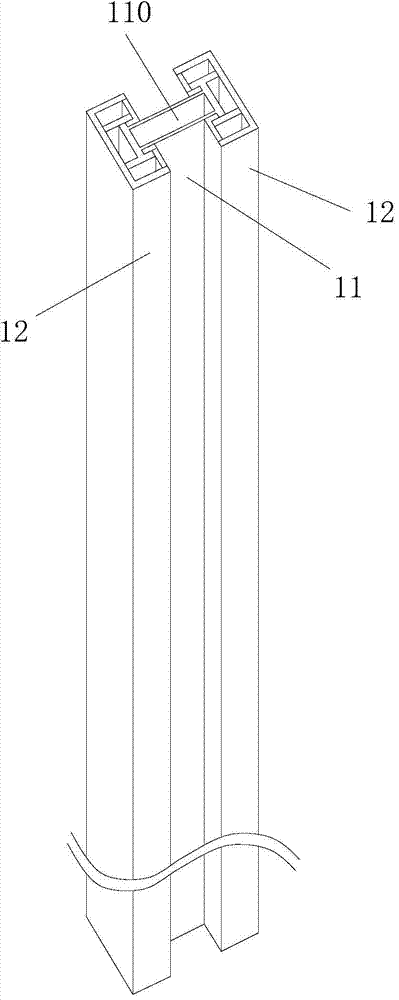
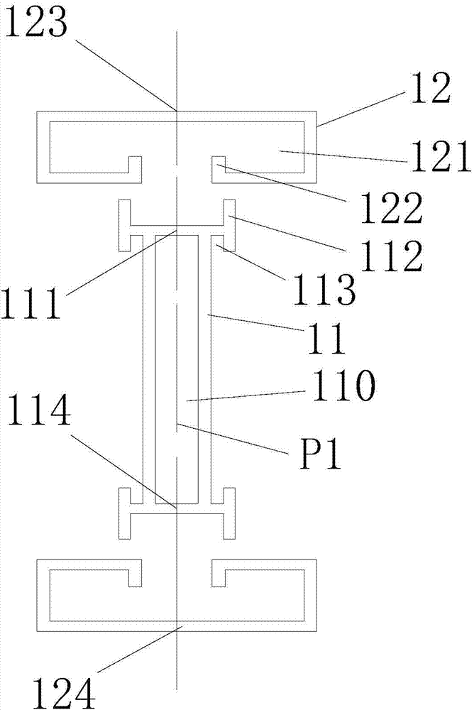
[0046] seefigure 1 and 2 , The inlaid I-shaped pipe described in this embodiment is provided with one connecting part 11 and two symmetrically arranged side inlaid parts 12 .
[0047] The coupling part 11 is provided with a longitudinal transparent cavity 110, and the ends of the coupling part 11 on both sides in the longitudinal direction have a longitudinal joint structure with a longitudinal joint strip 112 and a longitudinal joint groove 113, and the side joint part 12 has a There is a longitudinal seaming structure of the longitudinal seaming groove 121 and the longitudinal seaming bar 122 matched with the coupling part 11, and the coupling part 11 and the two side seaming parts 12 are separated from each other through the respective longitudinal seaming structures. Join and extend longitudinally through the seams. The cross-sectional structure of the spliced I-shaped pipe is longitudinal axis symmetric and transverse axis ...
Embodiment 2
[0049] Embodiment 2 (inlaid I-shaped tube)
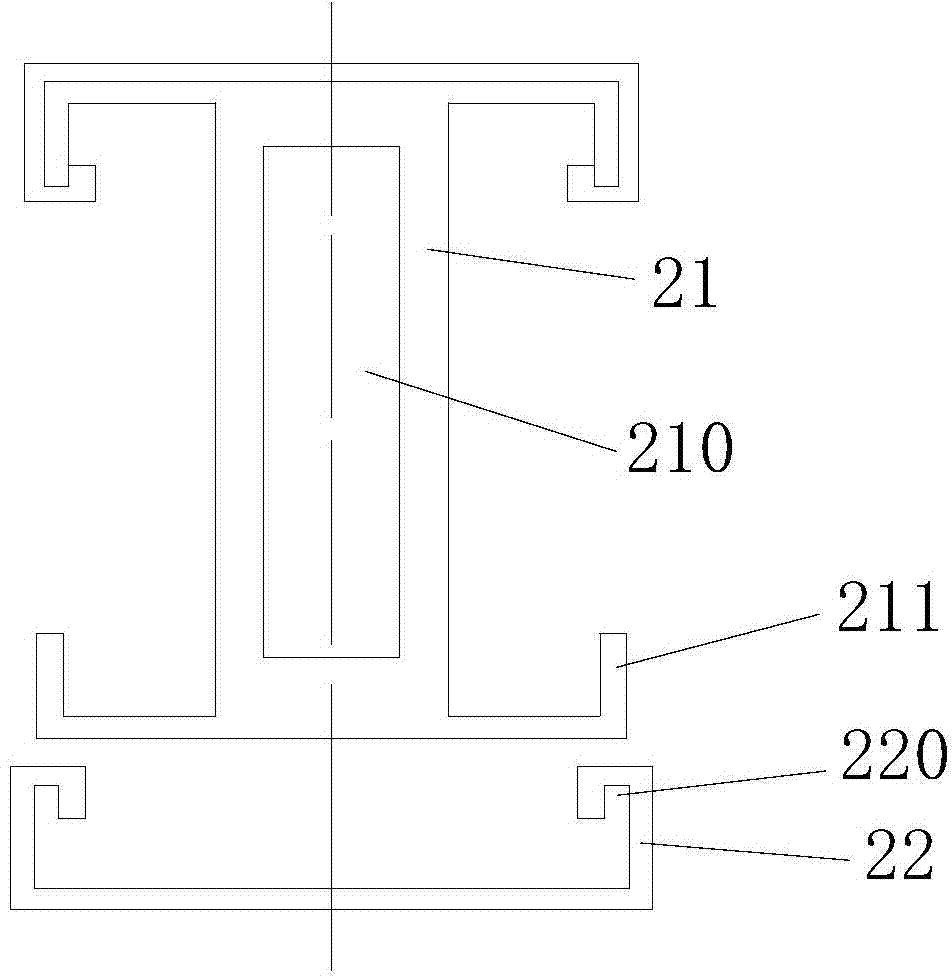
[0050] see image 3 , similar to Embodiment 1, the difference is that there is only one side fitting part 22, and only one side end of the connecting part 21 is provided with a longitudinal fitting structure with a fitting strip 211. The side setting part 22 is provided with a fitting groove 220 . The coupling part 21 is only interspersed with one side setting part 22 along the longitudinal direction. The fitting strip 211 fits with the fitting groove 220 . The structure of the connecting part 21 and the side setting part 22 after inserting and fitting is the same as that of the other end of the connecting part 21 . The connecting part 21 and the side setting part 22 are also jointed along the longitudinal direction. Reference 210 designates the longitudinal through cavity of the coupling part 21 . The cross-sectional structure of the spliced I-shaped pipe is symmetrical to the longitudinal axis.
Embodiment 3
[0051] Embodiment 3 (inlaid I-shaped tube)
[0052] see Figure 4 , similar to Embodiment 1, the difference is that the longitudinal embedding strips 311 at both ends of the coupling member 31 surround a rectangular ring groove 3111 . The fitting strips 311 at both ends of the coupling part 31 are matched with the fitting grooves 321 of the side fitting part 32 . The connecting part 31 and the side setting part 32 are also jointed along the longitudinal direction. Reference 310 designates the longitudinal through cavity of the coupling part 31 .
PUM
 Abstract
Description
Claims
Application Information
 - R&D
- Intellectual Property
- Life Sciences
- Materials
- Tech Scout
- Unparalleled Data Quality
- Higher Quality Content
- 60% Fewer Hallucinations
Browse by: Latest US Patents, China's latest patents, Technical Efficacy Thesaurus, Application Domain, Technology Topic, Popular Technical Reports.
© 2025 PatSnap. All rights reserved.Legal|Privacy policy|Modern Slavery Act Transparency Statement|Sitemap|About US| Contact US: help@patsnap.com


