Energy-gathering buffering device for improving tunnel smooth blasting effect and blasting method utilizing same

A technology of smooth blasting and buffer devices, which is applied in blasting and other directions, can solve the problems of uneven transmission of detonation waves, weak blasting directivity, and difficulty in keeping excavation contour lines from exceeding or undershooting, so as to prevent mixing, Effects that increase stability and usability

Active Publication Date: 2021-06-22
NANJING UNIV OF TECH +1
8 Cites 0 Cited by

AI-Extracted Technical Summary

Problems solved by technology

In the prior art, the contact gap between the charge column and the blast hole is large at the top and small at the bottom, the detonation wave is transmitted unevenly in the blast hole, ...

Method used

Concrete, energy-absorbing foam 6 is polyurethane foam, and flame-retardant cloth 7 is glass fiber cloth, and glass fiber cloth plays flame-retardant effect, and polyurethane foam plays energy-absorbing effect, and glass fiber cloth is bonded around polyurethane foam by glue. The present invention can adaptively change the volumes of the energy-absorbing material part 3 and the explosive part 4 through the setting of the partition plate 2, so as to adapt to different sizes of charge coils 5 for installation, so as to meet the on-site environment of different surrounding rock qualities. Since the pipe body of the PVC outer pipe 1 is highly flexible, the PVC outer pipe 1 with greater rotation flexibility is prone to overall distortion during the installation and alignment process, so the length of each section of the PVC outer pipe 1 does not exceed 2m. The arrangement of the energy-absorbing foam 6 in the present invention can absorb the blasting energy that cannot be blocked, and the partition board 2 can reflect the energy during blasting and effectively guide the energy generated during the blasting. The foam 6 can be separated to effectively prevent the mixing of the two, which increases the stability and practicability of the present invention. In this embodiment, the central angle corresponding to the energy-absorbing material part 3 is not greater than 120 degrees, and the central angle corresponding to the explosive part 4 is not less than 240 degrees. In the present invention, the central angle corresponding to the energy-absorbing material part 3 and the explosive part 4 correspond The size of the central angle can be selected according to the needs of on-site blasting. Through factory prefabrication, the on-site installation time can be reduced, while ensuring the blasting power and reducing the disturbance to the surrounding rock.
Preferably as above-mentioned embodim...

Abstract

The invention relates to an energy-gathering buffering device for improving the tunnel smooth blasting effect, which comprises a plurality of PVC outer pipes which are detachably connected and partition plates arranged in the PVC outer pipes. The partition plates are used for blocking and guiding energy during blasting, the inner walls of the PVC outer pipes are partitioned by the partition plates in the circumferential direction into energy-absorbing material parts and explosive parts, the central angle corresponding to each energy-absorbing material part is smaller than that corresponding to the corresponding explosive part, the explosive parts are used for installing explosive cartridges, energy-absorbing foam is installed in the energy-absorbing material parts and used for reducing disturbance and damage to surrounding rock on the outer side of an excavation contour line during explosion, and flame-retardant cloth is attached to the outer side of the energy-absorbing foam. According to the energy-gathering buffering device for improving the tunnel smooth blasting effect, through the arrangement of the partition plates, the volumes of the energy absorption material parts and the explosive parts can be adaptively changed so as to adapt to installation of explosive cartridges of different sizes, and the requirements of the field environments of different surrounding rock qualities can be met; and the energy-absorbing foam is arranged, so that explosion energy which cannot be blocked can be absorbed, the partition plates can reflect the energy during explosion, and the energy generated during explosion can be effectively guided.

Application Domain

Technology Topic

Image

  • Energy-gathering buffering device for improving tunnel smooth blasting effect and blasting method utilizing same
  • Energy-gathering buffering device for improving tunnel smooth blasting effect and blasting method utilizing same
  • Energy-gathering buffering device for improving tunnel smooth blasting effect and blasting method utilizing same

Examples

  • Experimental program(1)

Example Embodiment

[0031] The present invention will be further described below with reference to the accompanying drawings. The following examples are for more clearly explaining the technical solutions of the present invention without limiting the scope of the invention.
[0032] In the description of the present invention, it is to be described, which belongs to "center", "upper", "lower", "left", "right", "vertical", "horizontal", "inside", "outside", etc. The orientation or positional relationship indicated is based on the orientation or positional relationship shown in the drawings, is merely intended to describe the present invention and simplified description, rather than indicating or implying that the device or component must have a particular orientation. Construct and operation, so it is not understood to be the limitation of the invention.
[0033] In the description of the present invention, it is to be described in that, unless otherwise expressly specified and defined, the term "mount", "connected", "connection" should be broadly understood, for example, can be a fixed connection, or a detachable connection. , Or integrated connection; can be mechanically connected, or electrical connection; may be a direct connection, or by indirect connection through an intermediate medium, it can be in the interior of the two elements. The specific meaning of the above terms in the present invention will be appreciated to those skilled in the art. This embodiment is written in a manner.
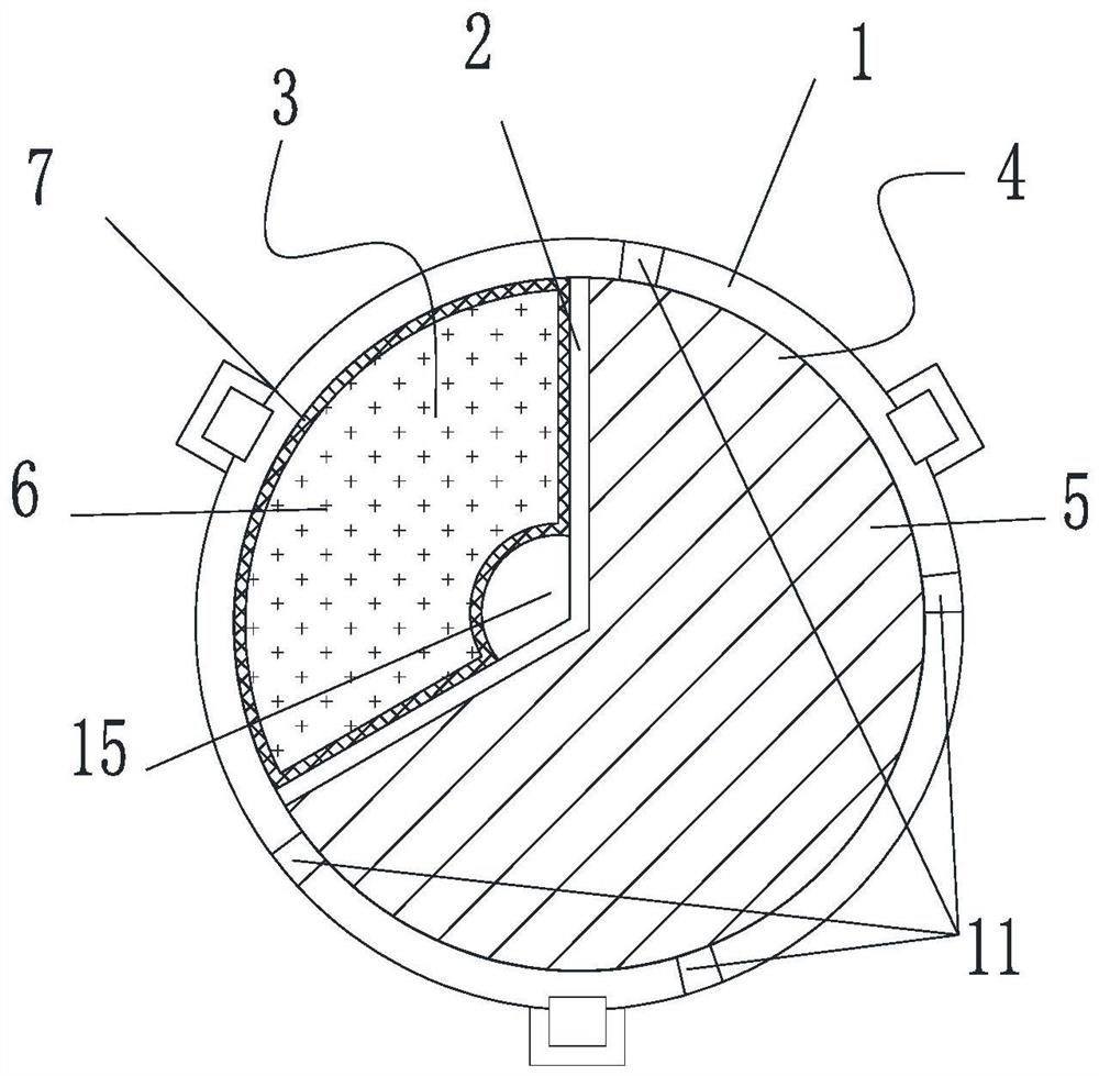
[0034] Append Figure 1-7 A polygraphic buffer device for improving the tunnel surface blasting effect, including a number of detachable connected PVC outer tubes and a separator 2 disposed within the PVC outer tube 1, the separator 2 is used to blast The energy is resistant and guided, and the separator 2 exists on the inner wall of the PVC outer tube 1 to form the suction material portion 3 and the explosive portion 4, and the core angle corresponding to the capability material portion 3 is smaller than the explosive portion 4. The center angle, the explosive portion 4 is used to mount the drug volume 5, and the suction foam 6 is mounted in the capability material portion 3 for reducing the disturbance and damage of the outer surrounding rock of the excavation profile when the explosion is used. A flame retardant 7 is attached.
[0035] Specifically, the suction foam 6 is a polyurethane foam, and the flame retardant cloth 7 is a glass fiber cloth, a glass fiber cloth plays a flame-retardant action, a polyurethane foam, and a glass fiber cloth is bonded to the polyurethane foam through the glue. The present invention can be adapted to the volume of the absorbent material portion 3 and the explosive portion 4 by the arrangement of the partition plate 2 to fit the different sizes of pharmaceutical rolls 5 to meet the on-site environment of different surrounding rocks. Since the tubular flexibility of the PVC outer tube 1 is large, the PVC outer tube 1 having a large rotating flexibility is easily distorted during mounting, so the length of the PVC outer tube 1 does not exceed 2 m. The arrangement of the adapter foam 6 in the present invention can be absorbed on the blasting energy of the barrier, and the partition plate 2 can reflect the energy of the blast, effectively guides the energy generated during blasting, and the separator 2 will pass the drug volume 5 and suck The foam 6 is separated, effectively prevents the mixing of both, increases the stability and practicability of the present invention. In the present embodiment, the center angle corresponding to the capability material portion 3 is no more than 120 degrees, and the center angle corresponding to the explosive portion 4 is not less than 240 degrees, and the core angle and explosive unit 4 corresponding to the capability material portion 3 in the present invention corresponds. The center angle size can be specific to the site blasting requires specific choices. Through the factory prefabricated form, the on-site installation time can be reduced, while ensuring that the blasting power is reduced to the surrounding rock.
[0036]Preferably, the PVC outer tube 1 is provided with at least three sets of pre-cleaves in the circumferential interval, and the pre-cleavage set is disposed outside the explosive portion 4 for reducing the loss of explosive blasting in the outside of the explosive portion 4.
[0037] Preferably, each set of pre-cleft holes include a plurality of through holes 11 disposed along the axial direction, and the through hole 11 is coupled to the explosive unit 4, and the cross section of the through hole 11 is arranged to rectangular. In the present embodiment, the length of the through hole 11 is provided to 5 to 8 mm, and the width is set to 1 to 2 mm. Through the arrangement of through the through hole 11, the explosive blasting power can be reduced outside of the explosive portion 4, and through the through hole 11 is blasting, the arrangement of the through hole 11 provides a viewing hole for the interval.
[0038] Preferably, each set of pre-cleft holes comprises a groove 16 disposed along the axial direction, the trench 16 is less than the wall thickness of the PVC outer tube 1, and the trench 16 is from the PVC outer tube 1. One end opening extends to the other end of the PVC outer tube 1. The cross section of the groove 16 is arranged in a trapezoidal shape having the inside of the groove 16, and the two sides of the trapezoid are parallel to each other, the trapezoidal upper bottom is disposed on one side of the explosive portion 4, the lower bottom of the trapezoid Set it away from the side of the explosive portion 4. The cross section of the groove 16 can also be set to a rectangle. The present invention can quickly crack the PVC outer tube 1 tube wall to improve the blasting effect by the arrangement of the trapezoidal groove 16.
[0039] Preferably, the central angle of the above-mentioned embodiment is formed in the axial center angle of the suction foam 6, and the flame retardant cloth 7 is closely fitted to the inner groove surface of the reserved groove, and the flame retardant cloth 7 and the partition 2 The reserved holes 15 extending along the length of the PVC outer tube are formed for the supply of explosion tubes. The reserved hole 15 causes the adjustment tube from the tube to the tail of the PVC outer tube 1, and then penetrate into the reservation 15 of the next section PVC outer tube 1.
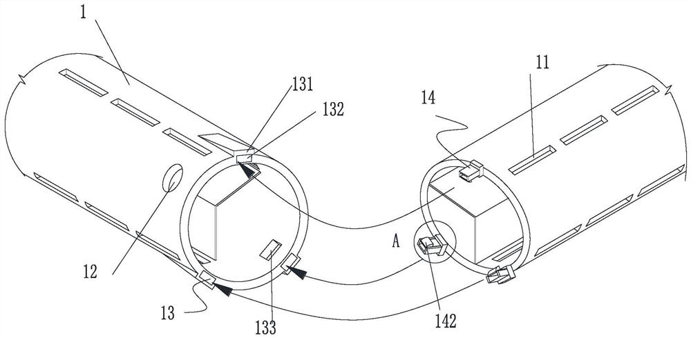
[0040] Preferably, one end of the PVC outer tube 1 is provided with a first connecting member 13, and the other end is provided with a second connecting member 14, and the first connector 13 is connected to the second connecting member 14. One end of the PVC outer tube 1 is provided with a first connecting member 13, and the other end is provided with a second connecting member 14, and the first connector 13 is connected to the second connecting member 14.
[0041] Preferably, the first connecting member 13 protrudes in the first boss 131 provided in the PVC outer tube 1 tube wall, and the first boss 131 is adjacent to the side of the PVC outer tube 1. The groove 132, the first boss 131 is opened, and the insertion groove 132 is inserted from the PVC outer tube 1 through the connecting groove 133, and the second connecting member 14 protrudes in the PVC outer tube 1, the second connecting member 14 includes The insertion groove 132 corresponds to the second boss 141, and the second boss 141 is opened in the direction of the PVC outer tube 1 axis, and the cartridge groove is resiliently connected to the card attachment 142, the card attachment 142 and The connection groove 133 corresponds to the side of the card attachment 142 as an arc surface toward the side of the PVC outer tube 1, facilitating the card attachment 142 into the connecting groove 133, and improves the convenience of the on-site installation.
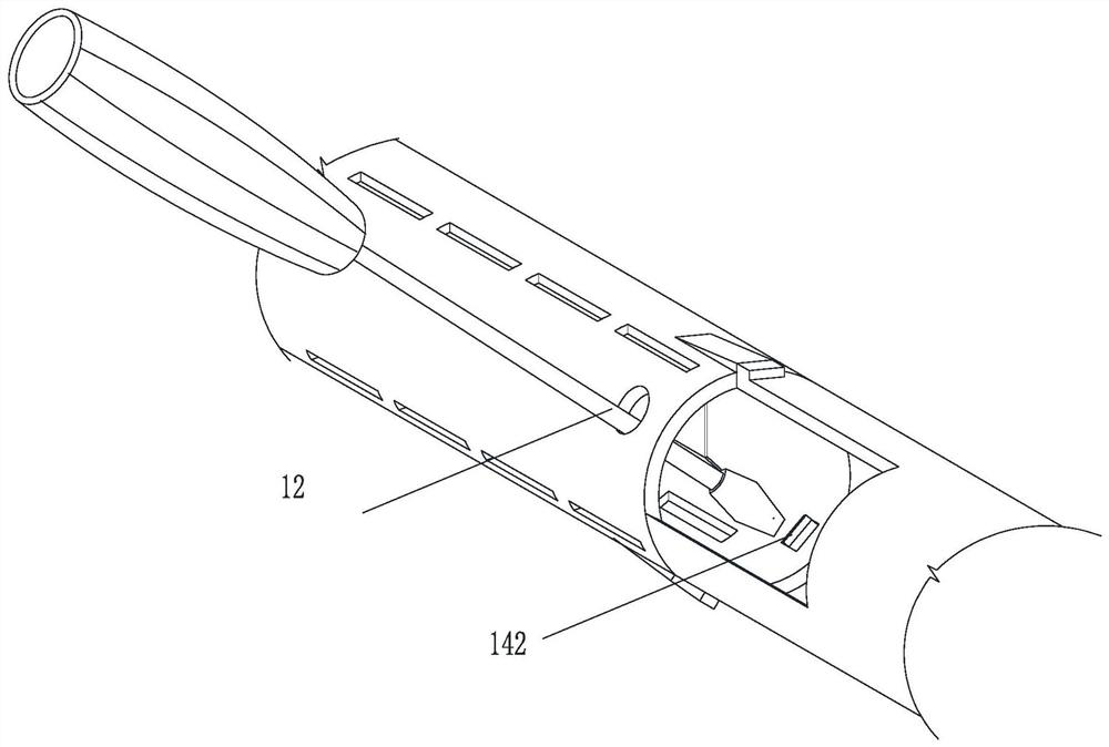
[0042] Preferably, the PVC outer tube 1 wall is opened, and the detachment hole 12 is disposed with respect to the connecting groove 133, and the number of disassembly holes 12 is consistent with the number of connecting grooves 133. The extended length of the separator 2 is smaller than the length of the PVC outer tube 1, and the distance from both ends of the partition plate 2 to the PVC outer tube 1 is greater than the distance between the detachment holes 12 to the PVC outer tube 1. The present invention facilitates the insertion of the screwdriver into the detachment hole 12 by the arrangement of the disassembly hole 12, so that the first connecting member 13 and the second connecting member 14 are removed by the PVC outer tube 1.
[0043] As the above embodiment, a method for increasing the concentration energy buffer device for improving the tunnel light surface blasting effect, including the following steps: Step 1, cutting the blade of the tunnel, cutting the eye, at the construction site to polyurethane foam Cutting, and coated with a glass fiber cloth over the polyurethane foam, the explosive coil 5 corresponding to the PVC outer tube 1, the polyurethane foam is installed in the factory prefabricated PVC outer tube 1 and the separator 2, and Explosion explosion equipment connection.
[0044] Step 2, using a slightly smaller PVC outer tube 1 test insertion of the cannon eye, whether there is a debris, the tube or cannon eye hole; if there is, it is handled, if it is, it will enter step three.
[0045] Step three, plug the single PVC outer tube 1 into the peripheral eye, then connect several PVC outer tubes 1.
[0046] Step 4, insert the guide tube into the reserved hole 15. When the artillery eye is collapsed, use the flat head screwdriver through the disassembly hole 12 to press the card pickup 142 and disassemble the PVC outer tube 1 to make a clear hole or re-drilling. If there is no fire hole, it is transferred to step five.
[0047] Step 5. Use a dedicated gun mud to block the eye of the gun and perform blasting.
[0048] In step three, when the PVC outer tube 1 is plugged in the hole, it is possible to rotate, and it is possible to ensure that the sides of the suction material is always near the excavation profile to ensure the direction of blasting energy to ensure the blasting effect.
[0049] Those skilled in the industry will be appreciated that the present invention is not limited by the above embodiments, and the above-described embodiments and descriptions are intended to illustrate the principles of the present invention, and the present invention will also have the present invention. Various changes and improvements, these changes and improvements have fallen within the scope of the claimed invention. The invention requires the scope of protection by the appended claims and their equivalents.

PUM

no PUM

Description & Claims & Application Information

We can also present the details of the Description, Claims and Application information to help users get a comprehensive understanding of the technical details of the patent, such as background art, summary of invention, brief description of drawings, description of embodiments, and other original content. On the other hand, users can also determine the specific scope of protection of the technology through the list of claims; as well as understand the changes in the life cycle of the technology with the presentation of the patent timeline. Login to view more.

Similar technology patents

Continuous mold cutting and folding mechanism

InactiveCN107214245AEffective constraintsAvoid mixingShaping toolsScrapPunching
Owner:JIANGSU BOJUN IND TECH

Sterile low bicarbonate dialysis concentrate solutions

InactiveUS7300674B2Avoid mixingBiocideSolvent extractionBicarbonate dialysisVenovenous Hemofiltration
Owner:APOTEX PHARMA HLDG

Valve casting wax mold surface silicon sol coating application process

ActiveCN111151713AReduce wasteAvoid mixingMoulding toolsFoundry mouldsCoated surfaceWaste material
Owner:东营一诚精密金属有限公司

Classification and recommendation of technical efficacy words

  • Improve usability and stability
  • Avoid mixing

Quick JavaWeb development method and system using native Web codes

InactiveCN104793961AImprove development speed and efficiencyImprove usability and stabilitySpecific program execution arrangementsVisulationData entity
Owner:黄伟

Method and device for enhancing reliability and availability of dual-computer clusters

ActiveCN105681074AAvoid Rack Power Down IssuesImprove usability and stabilityError preventionData switching networksCluster basedHigh availability
Owner:TOYOU FEIJI ELECTRONICS

Floating-suspending combined flexible water retaining curtain

ActiveCN104878728AIncrease flexibilityImprove usability and stabilityBarrages/weirsSingle pointPower station
Owner:THE FRONTIER TECH RES INST OF TIANJIN UNIV

Time phase encoding device and quantum key distribution system

ActiveCN113872701AConsistent lossImprove usability and stabilityKey distribution for secure communicationPhotonic quantum communicationDecoy statePhase modulation
Owner:北京正道量子科技有限公司

Deformable furniture with cabinet in bed

PendingCN108185715AReasonable structural designImprove usability and stabilityBedstandsSectional furniturePulling actionSitting room
Owner:林圣玉

Method, device and system of machine terminal communication

InactiveCN103200683AAvoid mixingIncrease profitAssess restrictionMachine-to-machine/machine-type communication serviceCarrier signalRadio frequency
Owner:CHINA MOBILE COMM GRP CO LTD

Micro component laser ablation isotope analyzing device and method

InactiveCN102455317AGeological application value enhancementAvoid mixingPreparing sample for investigationMaterial analysis by electric/magnetic meansPhysicsOrganic geochemistry
Owner:CHINA PETROLEUM & CHEM CORP +1
Why Eureka
Try Eureka