Power battery liquid cooling system performance testing device and testing method thereof

A technology for cooling systems and power batteries, applied in measuring devices, testing of machine/structural components, instruments, etc., can solve the problems of difficult to accurately define parameters, insufficient influence of bubbles, large differences in temperature distribution, etc. Product development efficiency, effect of wide applicability

Pending Publication Date: 2021-06-22
DONGFENG BEHR THERMAL SYST
View PDF3 Cites 2 Cited by
  • Summary
  • Abstract
  • Description
  • Claims
  • Application Information

AI Technical Summary

Problems solved by technology

[0007] In addition, the simulation of the temperature field is carried out through CFD. Since the simulation input conditions are based on theoretical physical parameters and empirical parameters, the simulation results are quite different from the actual temperature distribution, and there is no means of verification and analysis. impact is insufficient
Since the battery and the liquid cooling plate are installed in the box, the thermally conductive silicone pad and the support pad will be compressed to a certain extent. The support pads of different materials and thicknesses have different compression forces corresponding to the same compression rate. The thermally conductive silicone pads of different materials and thicknesses, Under different compression forces, the material thermal resistance will also change, and it is difficult to accurately define various parameters for the input of CFD simulation
[0008] Therefore, in the current electric vehicle power battery thermal management industry, it is difficult to accurately verify the temperature uniformity performance index of the battery liquid cooling cooling plate

Method used


Image

  • Power battery liquid cooling system performance testing device and testing method thereof
  • Power battery liquid cooling system performance testing device and testing method thereof

Examples


Embodiment Construction

[0034] The present invention will be further described in detail below in conjunction with the accompanying drawings and specific embodiments.

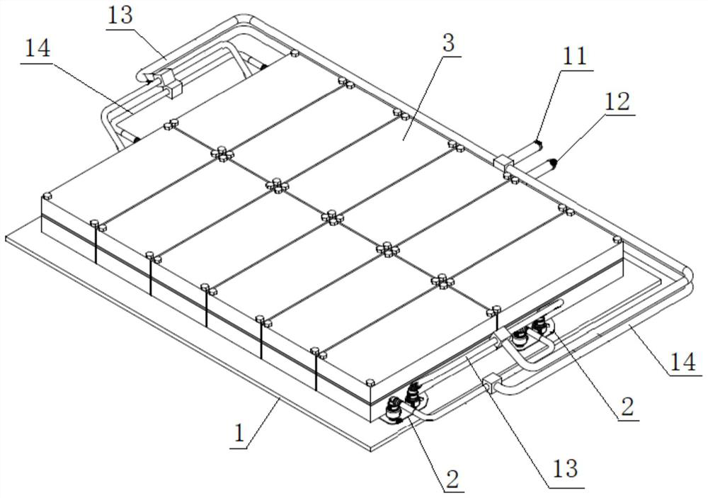
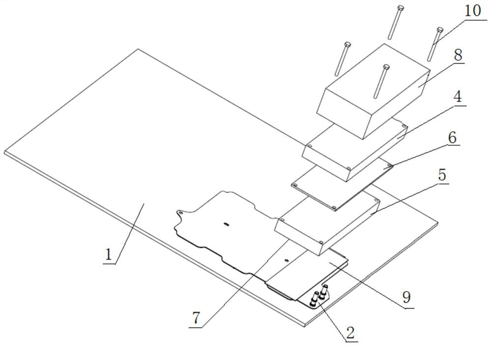
[0035] Such as figure 1 and figure 2 As shown, a power battery liquid cooling system performance test device of the present invention includes a mounting substrate 1, on which a liquid cooling plate 2 of the battery to be tested is installed, and a heat conduction pad is pasted on the upper surface of the liquid cooling plate 2 of the battery to be tested 9. The liquid inlet and outlet of the liquid cold plate 2 of the battery to be tested are connected to the cooling liquid supply system. Several simulated battery modules 3 are arranged on the upper surface of the liquid cold plate 2 of the battery to be tested. The simulated battery modules 3 It includes an upper aluminum plate 4 and a lower aluminum plate 5, a heating plate 6 is arranged between the upper aluminum plate 4 and the lower aluminum plate 5, and several thermocouples ...


PUM


Abstract

The invention relates to the technical field of new energy automobile power battery thermal management, and discloses a power battery liquid cooling system performance testing device which comprises a mounting substrate, a battery liquid cooling plate to be tested is mounted on the mounting substrate, and a liquid inlet and a liquid outlet of the battery liquid cooling plate to be tested are communicated with a cooling liquid supply system. A plurality of simulation battery modules are arranged on the upper surface of the battery liquid cooling plate to be tested, each simulation battery module comprises an upper aluminum plate and a lower aluminum plate, a heating plate is arranged between the upper aluminum plate and the lower aluminum plate, a plurality of thermocouples are attached to the lower bottom surface of the lower aluminum plate, and the thermocouples are connected with a test bed data acquisition instrument. The invention further discloses a testing method of the power battery liquid cooling system performance testing device. The power battery liquid cooling system performance testing device and the testing method thereof can simulate the actual working condition of the battery pack and test the cooling performance of the battery liquid cooling plate cooling system under the condition of no battery pack related environmental parts.

Description

technical field [0001] The invention relates to the technical field of thermal management of a power battery of a new energy vehicle, in particular to a performance test device and a test method for a liquid cooling system of a power battery. Background technique [0002] With the increase of the cruising range of new energy vehicles, the power battery pack (PACK) of new energy passenger vehicles basically uses ternary lithium batteries with higher energy density to replace lithium iron phosphate batteries with lower energy density. [0003] Since the working temperature of the battery determines its own safety, reliability, life and performance, according to the industry's PACK development level and technical requirements, the best working temperature of the battery is around 25°C to 40°C. And it is required that the temperature difference of the battery module is less than 5°C (the temperature value monitored by the battery management unit BMS). [0004] However, due to t...

Claims


Application Information

Patent Timeline
Patent Type & Authority Applications(China)
IPC IPC(8): G01M99/00
CPCG01M99/008G01M99/005
Inventor 吴杰钟昌聂盼孙樊廖星东袁雪娜
Owner DONGFENG BEHR THERMAL SYST
Why Eureka
Try Eureka