
Equipment for centralizedly treating used medical needle tubes

A centralized processing and equipment technology, applied in grain processing, solid separation, sieving, etc., can solve the problems of labor-intensive, incapable of needle crushing, poor processing effect, etc., and achieve the effect of reducing manual operation

Pending Publication Date: 2021-06-25
黄志武
View PDF8 Cites 9 Cited by
  • Summary
  • Abstract
  • Description
  • Claims
  • Application Information

AI Technical Summary

Problems solved by technology

[0002] Medical waste refers to the polluting waste produced by the hospital that has been in contact with the blood and body of patients, etc. It contains a large number of bacteria, viruses and chemicals, and is highly infectious, biologically toxic and corrosive. Used medical needles are It belongs to medical waste, the existing treatment equipment is very simple, can not achieve centralized treatment, and the treatment effect is poor, so it is necessary to design a treatment equipment
[0003] Patent application: CN107812578A, the publication date is 20180320, which discloses a needle tube processing device for gynecological blood drawing. By setting a switch mechanism and a feeding mechanism, it is convenient for medical staff to collect and process the needle tube. By enabling the motor to rotate, the The needle tubes in the collection bucket are crushed and broken into debris to facilitate the treatment of the needle tubes collected by the medical staff. The crushing device of this device cannot completely crush the needle tubes, and manual feeding is required, which consumes manpower

Method used


Image

  • Equipment for centralizedly treating used medical needle tubes
  • Equipment for centralizedly treating used medical needle tubes
  • Equipment for centralizedly treating used medical needle tubes

Examples


Embodiment 1

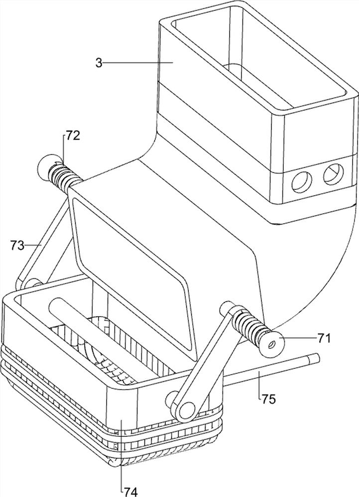
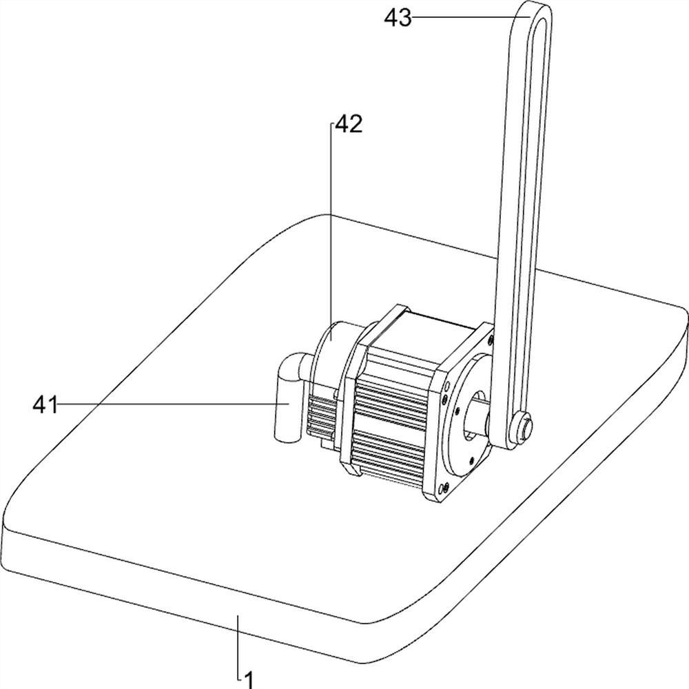
[0061] A centralized treatment device for medical needle tubes after use, such as figure 1 As shown, it includes a first support plate 1, a first support frame 2, a fluid frame 3, a power mechanism 4, a crushing mechanism 5, a feeding mechanism 6, a vibrating mechanism 7 and a collection box 10. The upper right of the first support plate 1 The first support frame 2 is provided on both sides of the front and back of the head, and a fluid frame 3 is connected between the left parts of the two first support frames 2, and a crushing mechanism 5 is arranged on the fluid frame 3, and the crushing mechanism 5 and the first support plate A power mechanism 4 is arranged between 1, a feeding mechanism 6 is arranged on the upper right side of the fluid frame 3, a vibrating mechanism 7 is arranged on the lower side of the fluid frame 3, and a collection box 10 is arranged on the left side of the first support plate 1.

[0062] When people need to process the needle tubes, they can use thi...

Embodiment 2

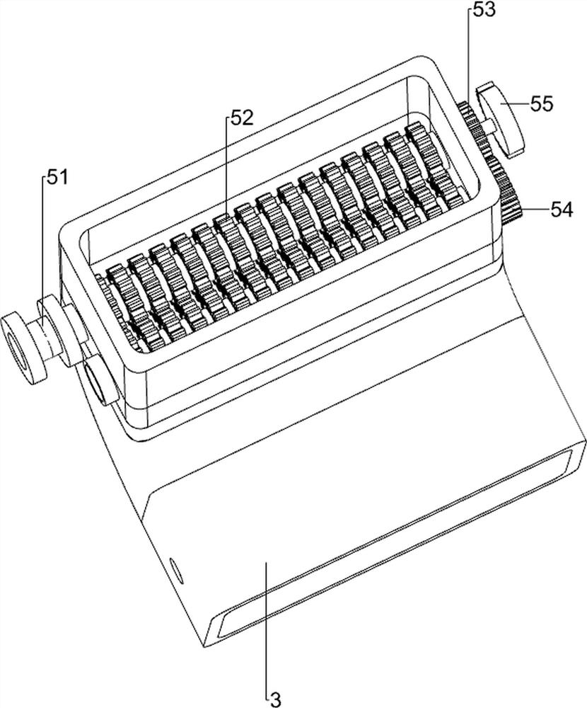
[0064] On the basis of Example 1, such as Figure 2-5 As shown, the crushing mechanism 5 includes a first rotating shaft 51, a crushing device 52, a first gear 53, a second gear 54 and a missing gear 55. The left and right sides of the fluid frame 3 are rotatably provided with the first rotating shaft 51, and the second A rotating shaft 51 is evenly provided with a plurality of crushers 52, the front side of the first rotating shaft 51 on the right side is provided with a first gear 53, the front side of the first rotating shaft 51 on the left side is provided with a second gear 54, and the first gear 53 It meshes with the second gear 54 , and the front side of the first rotating shaft 51 on the right is provided with a missing gear 55 .

[0065] After the needle tube in the feeding mechanism 6 falls into the fluid frame 3, people start the power mechanism 4, and the parts of the power mechanism 4 rotate to drive the first rotating shaft 51 on the right to rotate, so that the ...

Embodiment 3

[0073] On the basis of Example 2, such as Figure 6 and Figure 7 As shown, a first auxiliary mechanism 8 is also included. The first auxiliary mechanism 8 includes a fourth support frame 81, a first rack frame 82 and a third spring 83. The front part of the fluid frame 3 is provided with a fourth support frame 81. The fourth support frame 81 is slidably provided with a first rack frame 82, the missing gear 55 and the opener 64 are all matched with the first rack frame 82, and the first rack frame 82 is connected with the fourth support frame 81. There is a third spring 83 wound around the first rack frame 82 .

[0074] When the missing gear 55 rotates and contacts the first rack frame 82, the missing gear 55 drives the first rack frame 82 to move upward, and the third spring 83 is compressed. When the first rack frame 82 moves upward and touches the switch 64, The first rack frame 82 drives the switch 64 to move upward, and the first spring 65 is compressed, so that the nee...


PUM


Abstract

The invention relates to treatment equipment, in particular to equipment for centralizedly treating used medical needle tubes. The equipment for centralizedly treating the used medical needle tubes can realize automatic crushing, automatic feeding and automatic screening. The equipment for centralizedly treating the used medical needle tubes comprises a first supporting plate, first supporting frames, a fluid frame, a grinding mechanism, a power mechanism, a discharging mechanism, a vibration mechanism and a collecting box; the first supporting frames are arranged on the two sides of the first supporting plate; the fluid frame is connected between the two first supporting frames; the grinding mechanism is arranged on the fluid frame; the power mechanism is arranged between the grinding mechanism and the first supporting plate; the discharging mechanism is arranged on the upper side of the fluid frame; the vibration mechanism is arranged on the lower side of the fluid frame; and the collecting box is arranged on the first supporting plate. According to the equipment, through rotation of a first gear and a second gear, a driving gear rotates, and then a first rotating shaft on the left side rotates, so that grinding devices rotate to grind the needle tubes.

Description

technical field [0001] The invention relates to a processing device, in particular to a centralized processing device for used medical needle tubes. Background technique [0002] Medical waste refers to the polluting waste produced by the hospital that has been in contact with the blood and body of patients, etc. It contains a large number of bacteria, viruses and chemicals, and is highly infectious, biologically toxic and corrosive. Used medical needles are It belongs to medical waste, and the existing processing equipment is very simple, unable to achieve centralized processing, and the processing effect is poor, so it is necessary to design a processing equipment. [0003] Patent application: CN107812578A, the publication date is 20180320, which discloses a needle tube processing device for gynecological blood drawing. By setting a switch mechanism and a feeding mechanism, it is convenient for medical staff to collect and process the needle tube. By enabling the motor to ...

Claims


Application Information

Patent Timeline
Patent Type & Authority Applications(China)
IPC IPC(8): B02C4/08B02C4/42B02C4/28B02C23/10B02C23/02B09B3/00B09B5/00B07B1/28B07B1/42B07B1/46
CPCB09B3/0075B02C4/08B02C4/42B02C4/286B02C4/28B02C23/10B02C23/02B09B5/00B07B1/28B07B1/42B07B1/46B02C2201/06
Inventor 黄志武
Owner 黄志武
Learn More