Automatic profile steel punching device and punching method

An automatic punching and section steel technology, applied in the direction of punching tools, metal processing equipment, manufacturing tools, etc., can solve the problems of increased control difficulty, waste of resources, large load pressure of hydraulic pumps, etc., to reduce the oil circuit and the oil circuit control system. , The effect of avoiding excessive load and reducing the difficulty of punching

Active Publication Date: 2021-06-25
秦皇岛市国阳钢铁有限公司
View PDF9 Cites 0 Cited by
  • Summary
  • Abstract
  • Description
  • Claims
  • Application Information

AI Technical Summary

Problems solved by technology

This type of material has a certain appearance size, a certain cross-section shape, and certain mechanical and physical properties. Common section steels include I-shaped steel, channel steel, T-shaped steel, H-shaped steel, Z-shaped steel, and C-shaped steel. In the process of processing, it is a routine operation to punch the section steel. This process is usually carried out on the hydraulic punching machine. Taking the C-section steel as an example, it is required to punch out the hole pattern on different plates of the C-section steel. Therefore, the punching machine is required. There are separate hydraulic cylinders on the upper side, left side and right side for punching. The cost of the hydraulic punching machine increases, and at the same time, the oil circuit is complicated and the control is difficult. Multiple hydraulic cylinders cannot work at the same time, which will lead to excessive load pressure of the hydraulic pump, or even insufficient driving force of the hydraulic cylinder to complete the punching. Therefore, when a single hydraulic cylinder is working, the other hydraulic cylinders are in a standby state, resulting in high production efficiency. low, waste of resources

Method used


Image

  • Automatic profile steel punching device and punching method
  • Automatic profile steel punching device and punching method

Examples


Embodiment Construction

[0023] The following will clearly and completely describe the technical solutions in the embodiments of the present invention. Obviously, the described embodiments are only some of the embodiments of the present invention, rather than all the embodiments. Based on the embodiments of the present invention, all other embodiments obtained by persons of ordinary skill in the art without making creative efforts belong to the protection scope of the present invention.

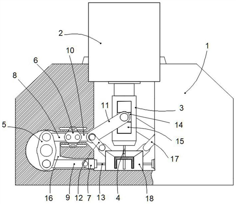
[0024] Such as figure 1 As shown, an automatic punching device for section steel in this embodiment includes a body 1, and an upper punching mechanism is arranged on the body 1, and the upper punching mechanism includes a hydraulic cylinder 2, which is sequentially connected to the output of the hydraulic cylinder 2. The mounting column 3 and the upper punching rod 4 on the end, the body 1 is provided with a punching die 18 below the upper punching rod 4; the punching die 18 should also be provided with a correspondi...


PUM


Abstract

The invention relates to an automatic profile steel punching device which comprises a machine body, and further comprises a side punching mechanism. The side punching mechanism comprises a lever, an upper sliding seat and a lower sliding seat; the lever is rotationally arranged in the machine body through a rotating shaft; the two ends of the lever are hinged to a first connecting rod and a second connecting rod respectively; the other end of the first connecting rod is hinged to the upper sliding seat; the other end of the second connecting rod is hinged to the lower sliding seat; a side punching rod is arranged at the other end of the lower sliding seat; a connecting rod is rotationally connected to the side edge of a mounting column; a third connecting rod is hinged to the bottom end of the connecting rod; a crank is rotationally connected onto a punching die; and the other end of the crank is rotationally connected to the joint of the connecting rod and the third connecting rod; According to the automatic profile steel punching device provided by the invention, the structure in the prior art is simplified, resources are saved, and the production efficiency is improved.

Description

technical field [0001] The invention relates to the technical field of profile production equipment, in particular to an automatic punching device and a punching method for profile steel. Background technique [0002] Section steel refers to a material with a certain geometric shape made of steel with certain strength and toughness through rolling, extrusion, casting and other processes. This type of material has a certain appearance size, a certain cross-section shape, and certain mechanical and physical properties. Common section steel includes I-shaped steel, channel steel, T-shaped steel, H-shaped steel, Z-shaped steel, and C-shaped steel. In the process of processing, it is a routine operation to punch the section steel. This process is usually carried out on the hydraulic punching machine. Taking C-section steel as an example, it is required to punch out the hole pattern on different plates of the C-section steel. Therefore, the punching machine is required. There are...

Claims


Application Information

Patent Timeline
Patent Type & Authority Applications(China)
IPC IPC(8): B21D28/34B21D28/24
CPCB21D28/34B21D28/243
Inventor 韩非李永恒杨跃辉郑万众
Owner 秦皇岛市国阳钢铁有限公司
Why Eureka
Try Eureka