Auxiliary device for steel pipe machining

A technology for auxiliary devices and steel pipes, applied in positioning devices, metal processing, metal processing equipment, etc., can solve the problems of high production cost, low application range, and inability to guarantee a single steel pipe, and achieve the effect of avoiding the inclination of steel pipes

Pending Publication Date: 2021-06-25
山西兴达通机电设备有限公司
View PDF7 Cites 6 Cited by
  • Summary
  • Abstract
  • Description
  • Claims
  • Application Information

AI Technical Summary

Problems solved by technology

[0003] Therefore, stacking several steel pipe blanks together and cutting one steel pipe at a time is a foreseeable way to effectively improve work efficiency, but for steel pipes with different diameters, it cannot be guaranteed that one steel pipe will be cut each time Processing steel pipes with specific pipe diameters has a low scope of application. For steel pipes with different pipe diameters, it is necessary to customize equipment of various specifications, and the production cost is high.

Method used


Image

  • Auxiliary device for steel pipe machining
  • Auxiliary device for steel pipe machining
  • Auxiliary device for steel pipe machining

Examples


Embodiment 1

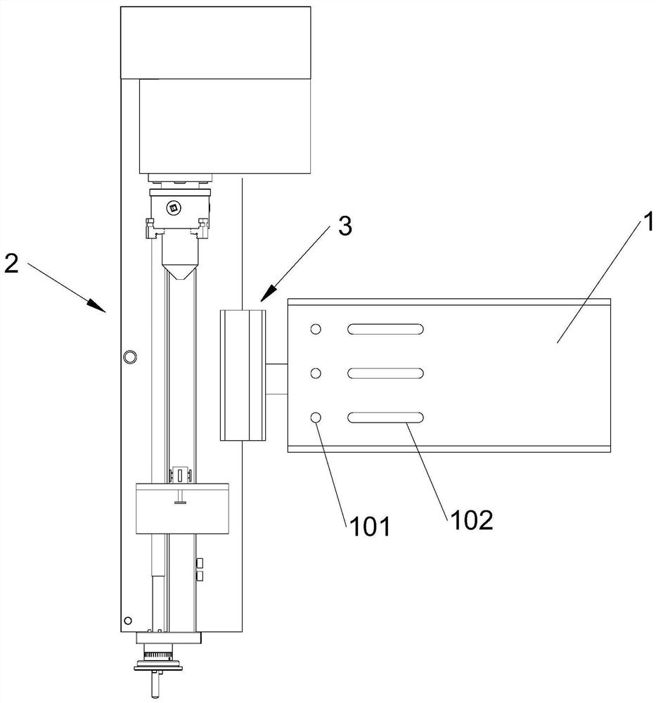
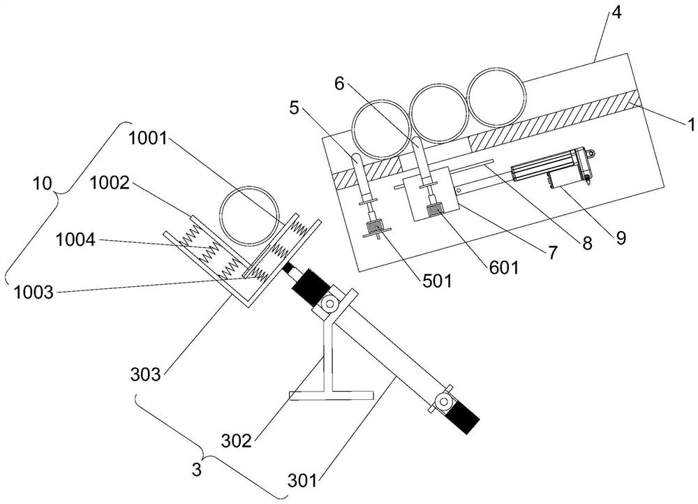
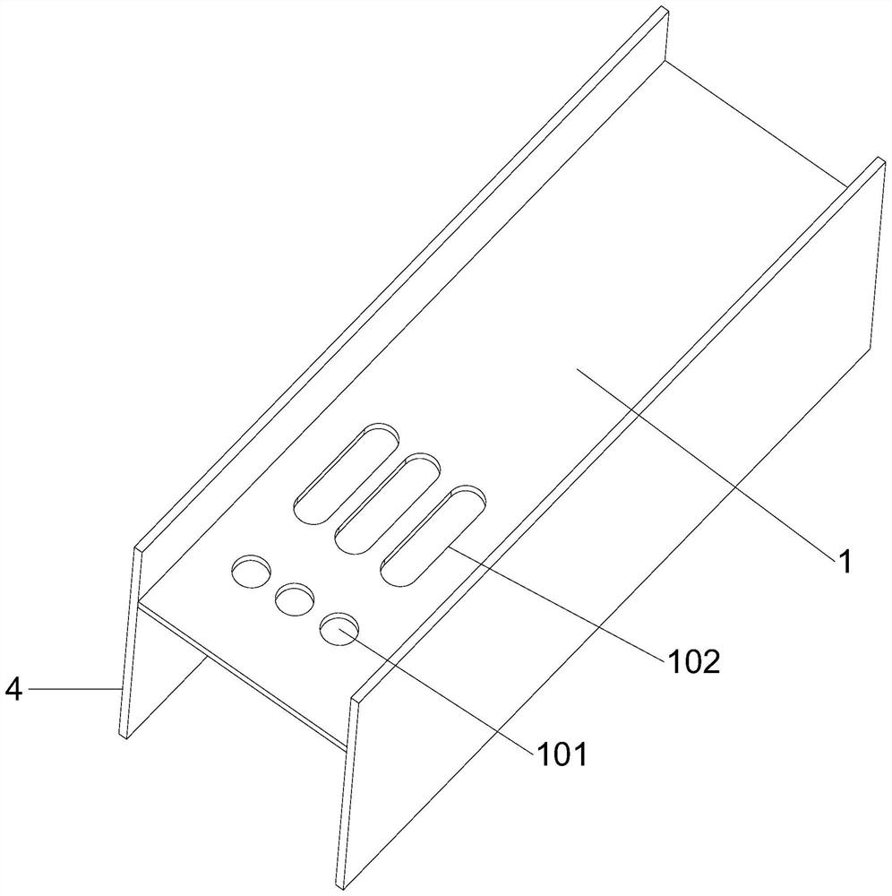
[0033]The auxiliary device for steel pipe processing of the present invention comprises clamping tooling 2 and a conveying plate 1 arranged side by side, the conveying plate 1 is inclined downward along the direction close to the clamping tooling 2, side guard plates 4 are arranged on both sides of the conveying plate 1, The lower end of the conveying plate 1 is provided with a through hole 101, and the first limit rod 5 that can move up and down is provided through the through hole 101. The conveying plate 1 is also provided with a chute 102, and a chute 102 is provided with a The second limit rod 6 for lifting and moving, the lower end of the second limit rod 6 is provided with a fixed box 7, the outer wall of the fixed box 7 is provided with a power assembly 9 for pushing the fixed box 7 to move along the direction of the chute 102, and the clamping tool 2 and the conveying plate 1 are also provided with a transfer assembly 3, the transfer assembly 3 is arranged obliquely an...

Embodiment 2

[0036] This embodiment is further optimized on the basis of Embodiment 1 as follows: a plurality of through holes 101 are arranged side by side, each through hole 101 is provided with a first stop rod 5, and the lower ends of all first stop rods 5 A connecting plate is provided, and a first hydraulic cylinder 501 is provided at the lower end of the connecting plate, and the first hydraulic cylinder 501 is installed on the side wall of the side guard plate 4 . A second hydraulic cylinder 601 is arranged inside the fixed box 7 , and the telescopic shaft of the second hydraulic cylinder 601 is connected to the second limiting rod 6 , and the second limiting rod 6 runs through the outer wall of the upper end of the fixed box 7 . The outer walls on both sides of the fixed box 7 are provided with guide blocks, and the inner walls of the two side guards 4 are provided with guide grooves 8 that are compatible with the guide blocks. The power assembly 9 is an electric push rod installed...

Embodiment 3

[0039] This embodiment is further optimized on the basis of Embodiment 1 as follows: the transfer assembly 3 includes a support plate 303, a third hydraulic cylinder 301 and a fixed frame 302; The plate 303 is connected to the third hydraulic cylinder 301, and the supporting plate 303 is bent downward to form a groove for supporting the steel pipe, and the buffer assembly 10 for buffering the steel pipe is arranged in the groove. The buffer assembly 10 includes a first positioning plate 1001, a second positioning plate 1002, a first buffer spring 1003 and a second buffer spring 1004, the first positioning plate 1001 is inclined downward along the direction that the conveying plate 1 points to the clamping tool 2, and the second The lower ends of the positioning plate 1002 and the first positioning plate 1001 are connected to each other, the planes where the first positioning plate 1001 and the second positioning plate 1002 are located are perpendicular to each other, and the fi...


PUM


Abstract

The invention discloses an auxiliary device for steel pipe machining, and relates to the technical field of auxiliary devices for steel pipe machining. The auxiliary device comprises a clamping tool and a conveying plate which are arranged side by side, the conveying plate inclines downwards in the direction close to the clamping tool, side protection plates are arranged on the two sides of the conveying plate, a through hole is formed in the lower end of the conveying plate in a penetrating mode, a first limiting rod capable of moving in a lifting mode is arranged in the through hole in a penetrating mode, a sliding groove is further formed in the conveying plate in a penetrating mode, a second limiting rod capable of moving in a lifting mode is arranged in the sliding groove in a penetrating mode, a fixing box is arranged at the lower end of the second limiting rod, a power assembly used for pushing the fixing box to move in the direction of the sliding groove is arranged on the outer wall of the fixing box, and a transferring assembly is further arranged between the clamping tool and the conveying plate. The auxiliary device has the advantages that steel pipes with different pipe diameters can be conveyed and discharged, it is guaranteed that one steel pipe is discharged at a time, the steel pipe carrying time is shortened, the clamping and fixing time of adjacent steel pipes is shortened, and the working efficiency is improved.

Description

technical field [0001] The invention relates to the technical field of auxiliary devices for steel pipe processing, in particular to an auxiliary device for steel pipe processing. Background technique [0002] In the existing steel pipe production process, the steel pipe blank needs to be further processed, for example, the steel pipe needs to be bored at certain specific positions, or a specific position needs to be polished. In the process of processing, it is often necessary to transfer the steel pipe on the assembly line to a specific fixture for clamping. After the previous steel pipe is processed, the next steel pipe is clamped and fixed. However, in the current prior art, manual handling is often used, and the manual labor intensity is high, the gap time for steel pipe processing is long, and the work efficiency is low. Especially for steel pipes with larger quality, the above-mentioned disadvantages are more obvious. [0003] Therefore, stacking several steel pipe ...

Claims


Application Information

Patent Timeline
Patent Type & Authority Applications(China)
IPC IPC(8): B23B31/02B23B31/40B23Q3/12B23Q7/00B24B41/00B24B41/06
CPCB23Q7/00B23Q3/12B23B31/40B23B31/02B24B41/00B24B41/06
Inventor 王保林刘武荣闫建新郭建雄郭耀宗杨绍青
Owner 山西兴达通机电设备有限公司
Why Eureka
Try Eureka