Clamp for finish machining of gearbox shell and clamping method

A gearbox and housing technology, which is applied in the direction of manufacturing tools, metal processing equipment, metal processing machinery parts, etc., can solve the problem that the tightening fixture cannot guarantee the processing accuracy, etc., and achieve the effect of good consistency, not easy to deform, and ensure rigidity

Active Publication Date: 2021-06-25
ANHUI QUANCHAI ENGINE
View PDF10 Cites 6 Cited by
  • Summary
  • Abstract
  • Description
  • Claims
  • Application Information

AI Technical Summary

Problems solved by technology

[0006] The technical problem to be solved by the present invention is: how to solve the problem that the tightening fixture and the method in the finishing process of the gearbox housing cannot guarantee the machining accuracy

Method used


Image

  • Clamp for finish machining of gearbox shell and clamping method
  • Clamp for finish machining of gearbox shell and clamping method
  • Clamp for finish machining of gearbox shell and clamping method

Examples


Embodiment 1

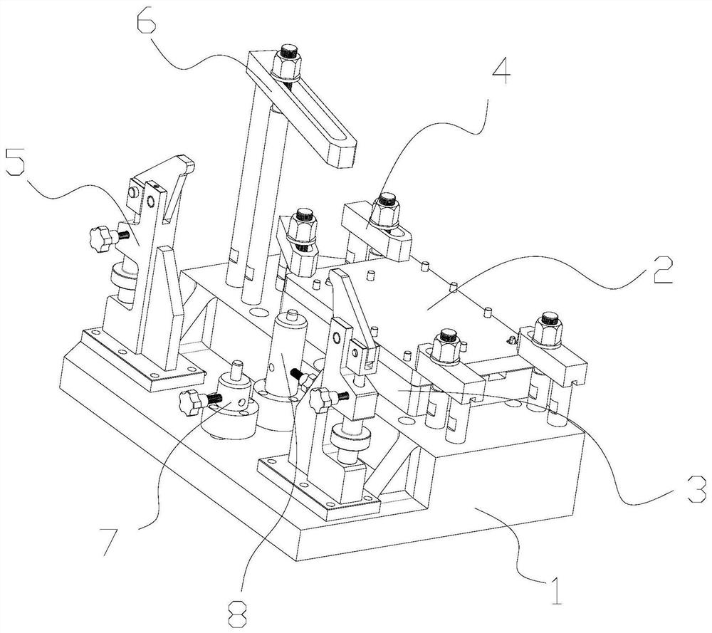
[0054] Such as figure 1 As shown, the fixture used for the finishing of the gearbox housing includes a base 1, a transition plate 2, a connecting plate 3, and a first pressing assembly 4 and an outer circle holding assembly 5 connected to the top surface of the base 1; The top surface of the transition plate 2 is connected to the window surface of the gearbox housing 9, the bottom surface of the transition plate 2 is connected to the top surface of the connecting plate 3, the bottom surface of the connecting plate 3 is connected to the base 1, and more The top end of the first pressing component 4 is pressed against the top surface of the transition plate 2 , and the outer circle clamping component 5 is clamped on the outer circle of the gearbox housing 9 .

[0055] The upper and lower sides of the base 1 are finished to ensure their flatness and parallelism, which can effectively ensure the overall rigidity, flatness and parallelism. In order to adapt to the height difference...

Embodiment 2

[0063] Such as Figure 8 As shown, on the basis of the first embodiment above, in this embodiment, the first pressing assembly 4 includes a first support rod 41, a first screw rod 42, a first pressure plate 43, and a first locking nut 44, so that The first support rod 41 and the first screw rod 42 are arranged at intervals, and the two are fixedly connected to the base 1 by means of bolts, etc., and one end of the first pressure plate 43 is hinged to the top end of the first support rod 41 , the other end of the first pressure plate 43 has a waist hole, the top of the first screw 42 passes through the waist hole, the first lock nut 44 is connected to the top of the first screw 42 to press the first pressure plate 43 Immediately on the transition plate body 21 , there are four first pressing components 4 , which are symmetrically arranged along the vertical symmetrical plane in the center of the gearbox housing 9 .

[0064] In this embodiment, the jig used for the finishing of...

Embodiment 3

[0068] Such as Figure 8 As shown, on the basis of the above-mentioned embodiment, there are two outer circle clamping components 5, which are symmetrically arranged along the vertical symmetrical plane of the center of the gearbox housing 9 .

[0069] refer to Figure 9 As shown, the outer circle tightening assembly 5 includes a support block 51, a lifting screw 52, ​​a lifting nut 53, an abutment plate 54, and a fastening bolt 55;

[0070] The support block 51 is an inverted F-shaped structure, the bottom of which is connected to the base 1, and reinforcement ribs are added to the side, the side of the support block 51 has a U-shaped notch, and the top has an L-shaped notch. The lifting nut 53 Located in the U-shaped groove of the support block 51, the lifting screw 52 vertically passes through the upper side of the U-shaped groove. Hinged, the bottom end of the lifting screw 52 is threadedly connected to the lifting nut 53, the middle part of the abutment plate 54 is hing...


PUM


Abstract

The invention discloses a clamp for finish machining of a gearbox shell. The clamp for finish machining of the gearbox shell comprises a base, a transition plate, a connecting plate, a first pressing assemblies and an outer circle holding assembly, wherein the first pressing assemblies and the outer circle holding assembly are connected to the top face of the base, the top face of the transition plate is connected with the window face of the gearbox shell, the bottom face of the transition plate is connected with the top face of the connecting plate, the bottom face of the connecting plate is connected with the base, the top ends of the multiple first pressing assemblies are pressed on the top face of the transition plate, and the outer circle holding assembly is clamped on the outer circle of the gearbox shell. The invention further discloses a clamping method of the clamp. The clamp for finish machining of the gearbox shell has the beneficial effects that the transition plate is adopted for connection, stable clamping and effective clamping and supporting are achieved, the size and precision of finish machining holes of the gearbox shell can be guaranteed, stability and reliability are achieved, and consistency is good.

Description

technical field [0001] The invention relates to a jig, in particular to a jig used for machining a gearbox casing. Background technique [0002] In the prior art, when finishing the gearbox housing (processing some holes and surfaces with high precision requirements), the window faces downward, and the window surface and two positioning pins are used for positioning. There is no suitable pressing position, such as directly pressing the transmission The box shell itself, the workpiece is not clamped tightly, can be shaken manually, and the high-precision hole is easily deformed, and an ellipse will be processed, and the coaxiality of the hole and the parallelism of the axis cannot be guaranteed. [0003] For example, the application number 201910170666.4, a gearbox housing processing jig, is characterized in that: the gearbox housing processing jig includes a bottom plate (1), a vertical plate (2), a rib plate (3), a rectangular opening (4), Special-shaped mouth (5), cylinde...

Claims


Application Information

Patent Timeline
Patent Type & Authority Applications(China)
IPC IPC(8): B23Q3/06
CPCB23Q3/062Y02E10/72
Inventor 徐玉良黄长文唐来明谷林强王成陈冬
Owner ANHUI QUANCHAI ENGINE
Why Eureka
Try Eureka