
Clamp driven by motor

A motor-driven, fixture technology for climate sustainability, end-product manufacturing, metal processing, etc., to avoid shaking, tight connections, and overall compactness

Active Publication Date: 2021-06-25
杨其建
View PDF5 Cites 3 Cited by
  • Summary
  • Abstract
  • Description
  • Claims
  • Application Information

AI Technical Summary

Problems solved by technology

[0005] The embodiment of the present application provides a motor-driven clamp, which solves the technical problem of coordinating the intervention time and working time of multiple components in the clamp designed by using the principle of pneumatics in the prior art; achieves the execution of a complete set of operation actions by using a single motor technical effect

Method used


Image

  • Clamp driven by motor
  • Clamp driven by motor
  • Clamp driven by motor

Examples


Embodiment Construction

[0043] The serial numbers assigned to components in this document, such as "first", "second", etc., are only used to distinguish the described objects, and do not have any sequence or technical meaning. The "connection" and "connection" mentioned in this application all include direct and indirect connection (connection) unless otherwise specified. In the description of this application, it should be understood that the terms "upper", "lower", "front", "rear", "left", "right", "vertical", "horizontal", "top", The orientation or positional relationship indicated by "bottom", "inner", "outer", "clockwise", "counterclockwise", etc. is based on the orientation or positional relationship shown in the drawings, and is only for the convenience of describing the present application and simplifying the description , rather than indicating or implying that the device or element referred to must have a particular orientation, be constructed and operate in a particular orientation, and th...


PUM


Abstract

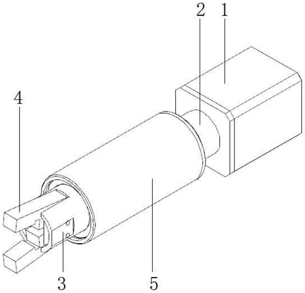
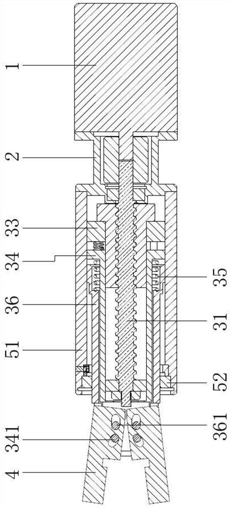
The embodiment of the invention provides a clamp driven by a motor, and belongs to the technical field of clamping devices. The clamp driven by the motor comprises the motor; an action mechanism, wherein the action mechanism comprises a lead screw; a lead screw sleeve, wherein the lead screw sleeve is arranged on the lead screw in a threaded connection and sleeving manner; a pushing assembly, wherein the pushing assembly comprises a first moving part and a second moving part, wherein the second moving part is movably connected with the first moving part, and in addition, an elastic space is formed between the second moving part and the first moving part; and a clamping jaw, wherein the clamping jaw is respectively connected with the first moving part and the second moving part. The lead screw sleeve acts on the pushing assembly, the clamping jaw is in a clamping state through change of the relative position between the first moving part and the second moving part, advancing of the lead screw sleeve is limited through a lead screw bearing, linear motion of the lead screw sleeve is changed into turnover motion, and the lead screw sleeve can indirectly drive the clamping jaw to conduct turnover motion. The technical effect of executing the whole set of operation actions by using the single motor is achieved.

Description

technical field [0001] The invention relates to the technical field of clamping devices, in particular to a motor-driven clamp. Background technique [0002] At present, when performing double-sided chamfering operations on workpieces such as bearing rings, it is necessary to turn over the bearing rings. [0003] The traditional non-standard automation design scheme is to split the execution process of the whole set of actions into multiple individual actions. When applied to the object of the bearing ring, it can be divided into the forward action, clamping action, flipping action, release action and retraction action. Based on the split research on actions, general non-standard automation will use a telescopic cylinder, an air claw and a rotating cylinder to combine the above actions. [0004] Therefore, the technical problem of the prior art is that the fixture designed using the principle of pneumatics needs to coordinate the intervention time and working time of multi...

Claims


Application Information

Patent Timeline
Patent Type & Authority Applications(China)
IPC IPC(8): B23Q7/04
CPCB23Q7/04Y02P70/50
Inventor 杨其建
Owner 杨其建
Learn More