Self-adhesive label manufacturing die-cutting machine and die-cutting method

A die-cutting machine and label technology, used in metal processing and other directions, can solve the problems of inaccurate die-cutting position, affecting the effect of die-cutting, and decreasing the tension of self-adhesive labels, so as to prevent stickers from remaining and not easy to deformation effect

Inactive Publication Date: 2021-06-25
刘芳芳
View PDF0 Cites 2 Cited by
  • Summary
  • Abstract
  • Description
  • Claims
  • Application Information

AI Technical Summary

Problems solved by technology

[0005] The invention can solve the problem that when the self-adhesive label is die-cut, the contact position between the cutter and the self-adhesive label is easy to stick to the self-adhesive residue. After working for a period of time, the self-adhesive residue is easy to accumulate on the cutting edge The incision of the knife affects the effect of die-cutting. At the same time, it is possible for the self-adhesive label to follow the movement of the cutter, and the self-adhesive label is lifted or even peeled off. When the self-adhesive label is die-cut, it is necessary to Stop the rewinding of the self-adhesive label before die-cutting. After stopping the rewinding of the self-adhesive label, the self-adhesive label is prone to reverse movement, resulting in a decrease in the tension of the self-adhesive label, thereby changing the position of the die-cutting In severe cases, it may cause inaccurate die-cutting positions, waste of self-adhesive labels, etc.

Method used


Image

  • Self-adhesive label manufacturing die-cutting machine and die-cutting method
  • Self-adhesive label manufacturing die-cutting machine and die-cutting method
  • Self-adhesive label manufacturing die-cutting machine and die-cutting method

Examples


Embodiment Construction

[0040] The embodiments of the present invention will be described in detail below with reference to the accompanying drawings, but the present invention can be implemented in many different ways defined and covered by the claims.

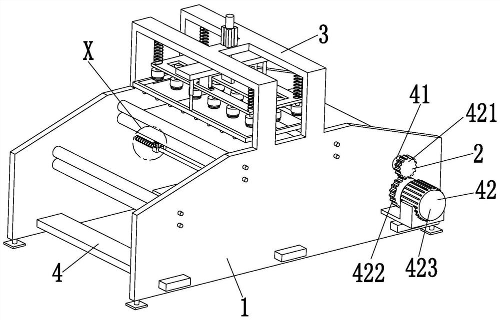
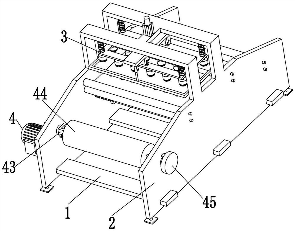
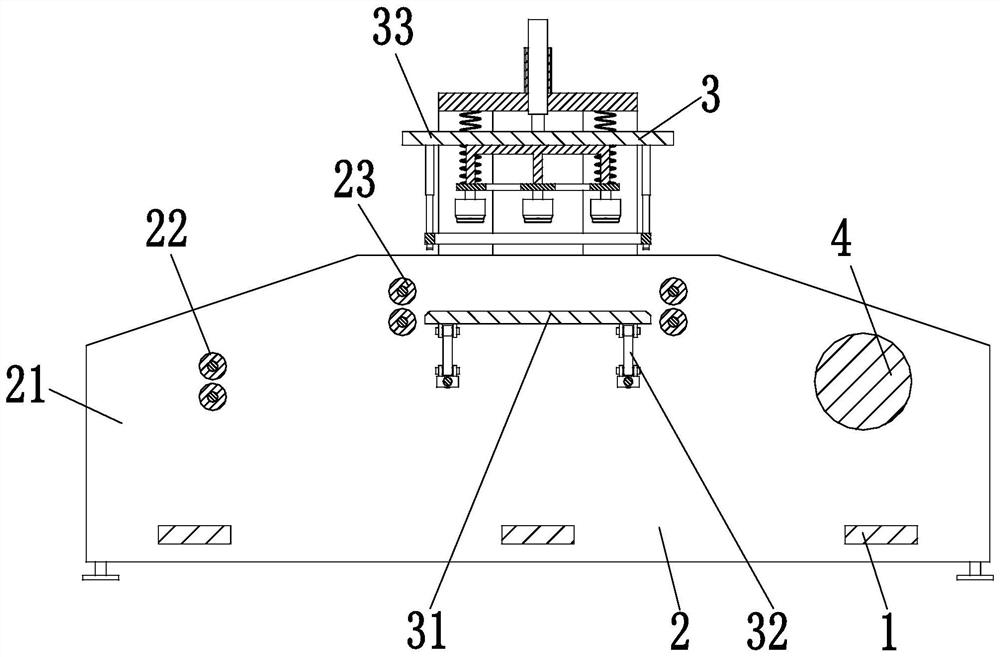
[0041] Such as Figure 1 to Figure 11 As shown, a self-adhesive label making die-cutting machine includes a connecting base plate 1, a mounting plate 2, a die-cutting device 3 and a driving device 4, and the front and rear sides of the connecting base plate 1 that are evenly arranged are symmetrically fixed with mounting plates 2. A die-cutting device 3 is installed in the middle between the installation plates 2, and a drive device 4 is installed on the right side between the installation plates 2.

[0042] Described installation board 2 comprises installation side board 21, No. 1 turning roller 22 and No. 2 turning roller 23, and the front and rear sides of the evenly arranged connection bottom plate 1 are symmetrically fixed with installation sid...


PUM


Abstract

The invention relates to a self-adhesive label manufacturing die-cutting machine and a die-cutting method. The self-adhesive label manufacturing die-cutting machine comprises connecting bottom plates, mounting plates, a die-cutting device and a driving device, wherein the mounting plates are symmetrically fixed on the front sides and the rear sides of the connecting bottom plates uniformly arranged, the die-cutting device is arranged in the middle portion between the mounting plates, and the driving device is arranged on the right side of a space between the mounting plates. The self-adhesive label manufacturing die-cutting machine and the die-cutting method can solve the problems that the die cutting effect is affected due to the fact that self-adhesive residues are prone to be accumulated at cutting edges of cutters during self-adhesive label die cutting, meanwhile, self-adhesive labels are taken up and even peeled off due to the fact that the self-adhesive labels possibly move along with the cutters, and the self-adhesive labels are wasted due to the fact that when the self-adhesive labels are subjected to die cutting treatment, winding of the self-adhesive labels needs to be stopped and then die cutting is carried out, at the moment, the self-adhesive labels are prone to reversely move, the tensioning degree of the self-adhesive labels is reduced, the die cutting positions are changed, and the die cutting positions possibly are inaccurate in serious cases.

Description

technical field [0001] The invention relates to the technical field of label preparation, in particular to a self-adhesive label making die-cutting machine and a die-cutting method. Background technique [0002] Self-adhesive is a kind of material, the material is made of paper, film or other special materials, the back is coated with adhesive, and a composite material with silicon-coated protective paper as the backing paper, and it becomes a finished product after printing, die-cutting, etc. Label. Common self-adhesive labels include drug labels, food labels, outer box labels, barcode labels, etc. Self-adhesive labels have the advantages of no pollution, saving labeling time, etc., and have a wide range of applications, convenient and fast. [0003] At present, when making self-adhesive labels, there are usually the following defects: 1. When the self-adhesive labels are die-cut, the contact position between the cutter and the self-adhesive labels is easy to stick with s...

Claims


Application Information

Patent Timeline
Patent Type & Authority Applications(China)
IPC IPC(8): B26F1/40B26D7/02B26D7/08B26D7/14B26D7/00
CPCB26D7/00B26D7/025B26D7/088B26D7/14B26F1/40
Inventor 刘芳芳
Owner 刘芳芳
Why Eureka
Try Eureka