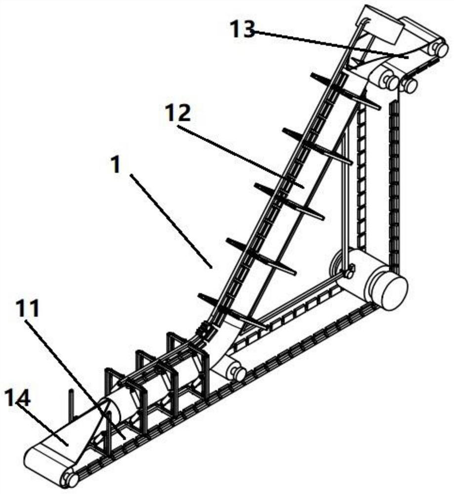
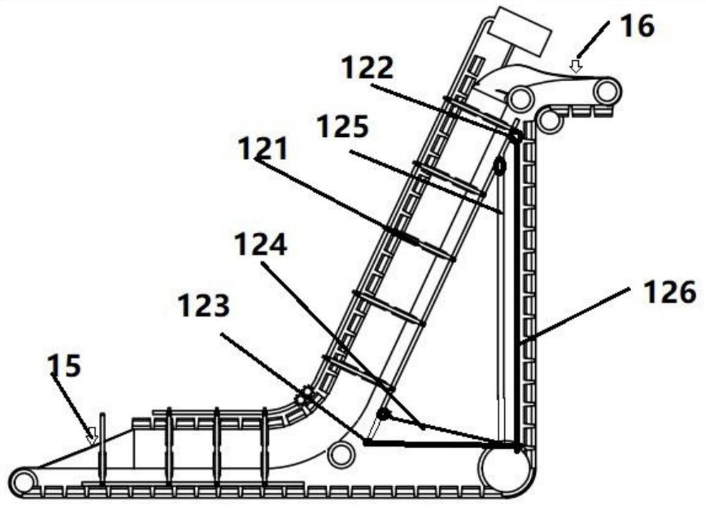
Control method of mixing and conveying device for civil engineering

A conveying device and civil engineering technology, applied in conveyor control devices, conveyors, mechanical conveyors, etc., can solve problems such as damage, excessive angle, and inability to achieve conveying, and achieve the effect of expanding the scope of application and realizing whether or not to accumulate.

Active Publication Date: 2021-06-25
GUANGXI TRANSPORTATION SCI & TECH GRP CO LTD +1
View PDF13 Cites 0 Cited by
  • Summary
  • Abstract
  • Description
  • Claims
  • Application Information

AI Technical Summary

Problems solved by technology

[0002] In the prior art, the circular pipe conveyor is often used in civil engineering operations to transport various excavated silt. Since it can be set as an airtight conveying method by using an ordinary conveyor belt, it is dust-proof, Factors such as conveying speed have been widely used. In order to meet the conveying operations at different heights, it is often set up as a Z-shaped conveying mechanism for lifting and conveying operations in civil engineering operations. However, in specific applications, the lifting angle may vary. Within a certain limit, the highest lifting angle is often set at about 30°. If the angle is too large, it cannot be effectively lifted, and the sediment material will accumulate at the starting position of the lifting end of the Z-shaped structure, causing the material to break through the circular pipe conveyor. The seal of the material will spill outside; similarly, when the material is conveyed from the high position to the low position during the two-way transportation, the material will also accumulate at the starting position of the lifting end of the Z-shaped structure due to gravity, which will also cause damage and cannot Realize effective conveying. For the screw conveyor, although it can realize the maximum lifting in the vertical direction, however, due to its special structure and cost considerations, it is difficult to realize long-distance conveying

Method used


Image

  • Control method of mixing and conveying device for civil engineering
  • Control method of mixing and conveying device for civil engineering
  • Control method of mixing and conveying device for civil engineering

Examples


Embodiment Construction

[0023] The present invention will be further described below in conjunction with specific embodiments. Among them, the accompanying drawings are only used for exemplary description, and they are only schematic diagrams, not physical drawings, and should not be construed as restrictions on this patent; in order to better illustrate the embodiments of the present invention, some parts of the accompanying drawings will be omitted, The enlargement or reduction does not represent the size of the actual product; it is understandable to those skilled in the art that some well-known structures and their descriptions in the accompanying drawings may be omitted.

[0024] The same or similar numbers in the drawings of the embodiments of the present invention correspond to the same or similar components; in the description of the present invention, it should be understood that if there are terms “upper”, “lower”, “left” and “right” The orientation or positional relationship indicated by e...


PUM


Abstract

The invention provides a control method of a mixing and conveying device for civil engineering. The control method specifically adopts a mode of combining a pipe belt conveyor and a spiral conveyor to realize lifting and conveying of silt materials in civil engineering operation, and is matched with a flow monitor to realize comparison of front and back flows, the positive rotating speed and the negative rotating speed of the spiral conveyor are controlled to avoid material accumulation, and therefore, the problem that the pipe belt conveyor cannot convey the materials in the direction of a high inclination angle is solved.

Description

technical field [0001] The invention relates to a control method of a conveying device in civil engineering, in particular to a control method of a mixed conveying device for civil engineering. Background technique [0002] In the prior art, round pipe conveyors are often used in civil engineering operations to transport various excavated sediments. Since they can be set up in a closed conveying mode by using ordinary conveyor belts, they are dust-proof, Factors such as conveying speed are widely used. In order to meet conveying operations at different heights, it is often set up as a zigzag conveying mechanism for lifting and conveying operations in civil operations. However, in specific applications, its lifting angle exists. To a certain limit, the highest lifting angle is often set at about 30°. If the angle is too large, it cannot be effectively lifted, which will cause the sediment material to accumulate at the starting position of the lifting end of the Z-shaped struc...

Claims


Application Information

Patent Timeline
Patent Type & Authority Applications(China)
IPC IPC(8): B65G37/00B65G43/08B65G43/00
CPCB65G37/00B65G43/08B65G43/00B65G2201/045B65G2203/04
Inventor 彭曦周武军王龙林于孟生王华王海华张磊李俊毅李丽琳何清
Owner GUANGXI TRANSPORTATION SCI & TECH GRP CO LTD
Why Eureka
Try Eureka