Tray conveying assembly line

A pallet conveying and assembly line technology, applied in the field of assembly line, can solve the problems of increasing the load of the assembly line, damage to the pallet, affecting the transportation of the assembly line, etc., and achieve the effect of ensuring balance, preventing tilt, and ensuring the stability of conveying

Inactive Publication Date: 2021-06-25
谢美玲
View PDF0 Cites 1 Cited by
  • Summary
  • Abstract
  • Description
  • Claims
  • Application Information

AI Technical Summary

Problems solved by technology

[0003] When using an assembly line to transport pallets, place the pallets on the assembly line for transportation and conduction. Since the pallets are mostly placed flat on the assembly line, if they collide with the side wall of the assembly line during the conveyance process, the pallets tend to tilt and get stuck on the assembly line. , causing the assembly line to be stuck, affecting the transportation of the assembly line, and the assembly line will generate a certain frictional resistance with the bottom of the pallet during the rotation process, which is easy to damage the pallet or increase the load of the assembly line, reducing the usability of the assembly line

Method used


Image

  • Tray conveying assembly line
  • Tray conveying assembly line
  • Tray conveying assembly line

Examples


Embodiment 1

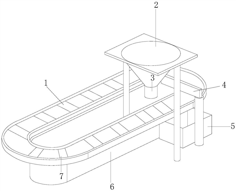
[0031] see figure 1 , the present invention provides a technical solution: a pallet conveying line, the structure of which includes a conveyor belt 1, a material tray 2, a discharge port 3, a height limit baffle 4, a placement frame 5, a main body 6, and an adjustment device 7. The conveyor belt 1 is integrated with the main body 6, a placement frame 5 is installed on one side of the main body 6, a height-limiting baffle 4 connected thereto is provided on the conveyor belt 1, and the conveyor belt 1 and the adjustment device 7 are movable. Together, the conveyor belt 1 is provided with a discharge port 3, and the discharge port 3 is fixedly connected with the tray 2.

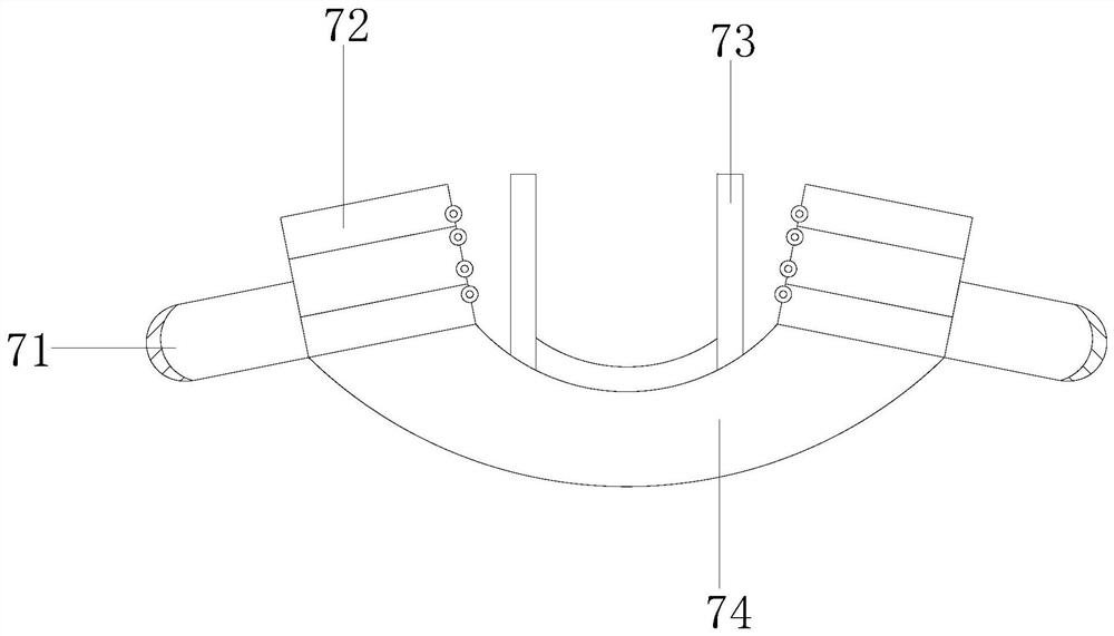
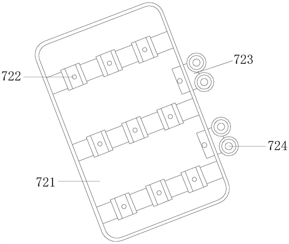
[0032] see figure 2 , the correcting device 7 includes a moving slide 71, a resisting piece 72, a holding seat 73, and a protective bracket 74. There are two moving slides 71, and the two moving slides 71 are symmetrically installed on two resisting On one side of the member 72, a protective bracket 74 conne...

Embodiment 2

[0042] see figure 1 , the present invention provides a technical solution: a pallet conveying line, the structure of which includes a conveyor belt 1, a material tray 2, a discharge port 3, a height limit baffle 4, a placement frame 5, a main body 6, and an adjustment device 7. The conveyor belt 1 is integrated with the main body 6, a placement frame 5 is installed on one side of the main body 6, a height-limiting baffle 4 connected thereto is provided on the conveyor belt 1, and the conveyor belt 1 and the adjustment device 7 are movable. Together, the conveyor belt 1 is provided with a discharge port 3, and the discharge port 3 is fixedly connected with the tray 2.

[0043] see figure 2 , the correcting device 7 includes a moving slide 71, a resisting piece 72, a holding seat 73, and a protective bracket 74. There are two moving slides 71, and the two moving slides 71 are symmetrically installed on two resisting On one side of the member 72, a protective bracket 74 conne...


PUM


Abstract

The invention discloses a tray conveying assembly line. The assembly line structurally comprises a conveying belt, a material tray, a discharging opening, a height limiting baffle, a containing frame, a main body and an aligning device. When the tray conveying assembly line is used, the tray is stably clamped on a deformation strip through cooperation of two connecting block limiting pieces, the deformation strip is assisted by a protection support in supporting and protecting the tray, the bottom of the tray is prevented from making contact with the conveying belt, an abutting piece is positioned by moving a sliding piece, rotating wheels can be stably matched with a sliding plate to drive the tray to move along with movement of the conveying belt, the tray is not prone to inclination and clamping stagnation due to the action of the shell in the conveying process, and normal conveying of the assembly line is guaranteed.

Description

technical field [0001] The invention relates to the field of assembly lines, in particular to a pallet conveying assembly line. Background technique [0002] In the factory automation production process, the application of the conveying line is very extensive. The assembly line means that the labor objects pass through each station in turn according to a certain process route, and complete the process work according to a uniform production speed. Each product needs to be processed in multiple processes. It can be formed, and the pallet is adjusted by the leveling element. When using the pallet conveying line, the areas that need to be improved: [0003] When using an assembly line to transport pallets, the pallets are placed on the assembly line for transportation and conduction. Since most of the pallets are directly placed on the assembly line, if they collide with the side wall of the assembly line during the transportation process, the pallet is prone to tilt and get stu...

Claims


Application Information

Patent Timeline
Patent Type & Authority Applications(China)
IPC IPC(8): B65G47/74B65G47/24
CPCB65G47/24B65G47/74
Inventor 刘雪凤
Owner 谢美玲
Why Eureka
Try Eureka