Air pressure printing and dyeing device
A pressurized device and air pressure technology, which is applied in the field of printing and dyeing, can solve the problems of high degree of intelligence and the inability to realize large-area uniform printing and dyeing of reserved printing and dyeing patterns, and achieve the effects of high degree of intelligence, thorough dyeing, and reduced defective rate
- Summary
- Abstract
- Description
- Claims
- Application Information
AI Technical Summary
Problems solved by technology
Method used
Image
Examples
Embodiment 1
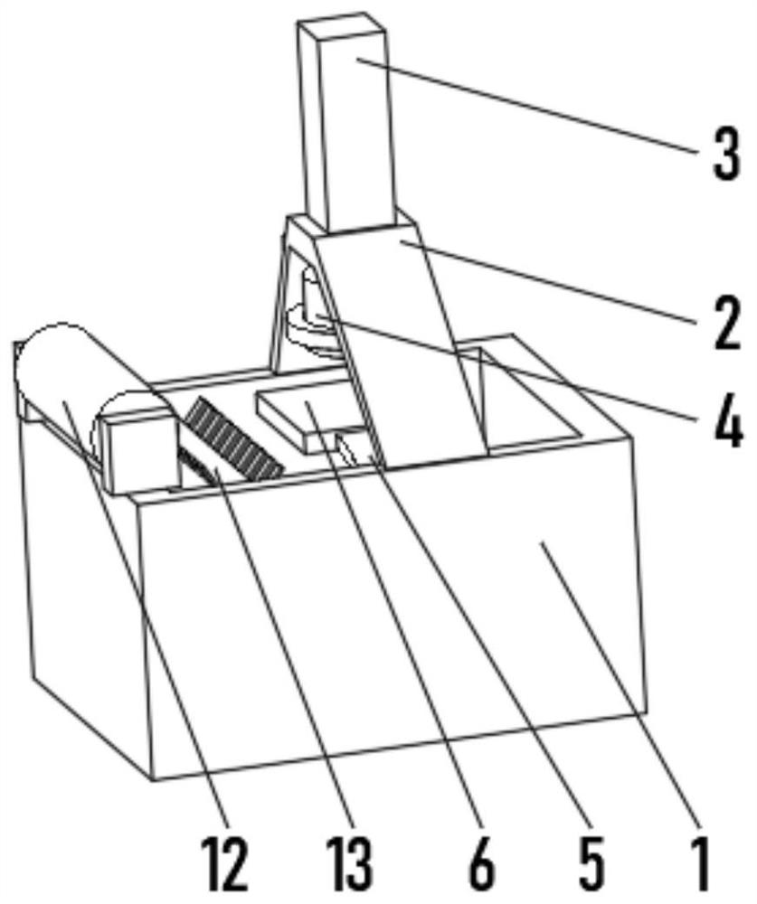
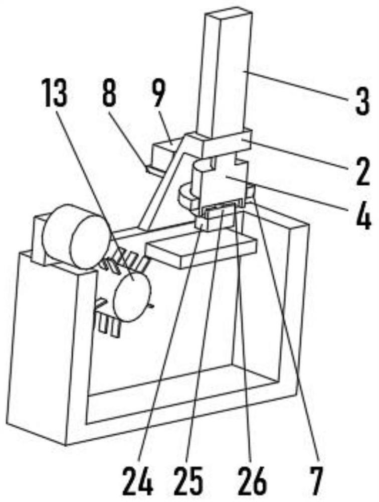
[0032] see Figure 1-2 The present invention provides a technical solution: a pneumatic printing and dyeing device, comprising a printing and dyeing barrel 1, a lifting cylinder 3 is installed on the top of the printing and dyeing barrel 1 through a printing and dyeing bracket 2, and the lifting oil cylinder 3 penetrates to one end below the printing and dyeing bracket 2. The pressure column 4 and the inner wall of the printing and dyeing barrel 1 are fixedly connected to the pressure-bearing plate 6 through the elastic plate 5 on both sides.
[0033] A feeding wheel 12 is installed on the top of the printing and dyeing barrel 1 , and a carding wheel 13 is rotatably connected to one end of the inner wall of the printing and dyeing barrel 1 near the feeding wheel 12 .
[0034] The bottom of the extrusion column 4 is installed with a printing and dyeing module 24 , the top of the printing and dyeing module 24 is fixedly connected with a cross bump 25 , and the bottom of the extr...
Embodiment 2
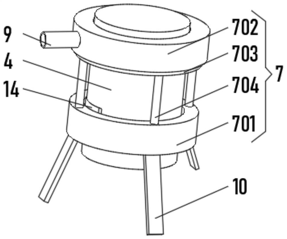
[0037] see Figure 1-4 , the present invention provides a technical solution: on the basis of the first embodiment, an air supply device 7 is installed on the outside of the extrusion column 4, a support plate 8 is fixedly connected to one side of the printing and dyeing bracket 2, and the top of the support plate 8 is fixedly connected with a The air pump 9, the air outlet of the air pump 9 penetrates the printing and dyeing support 2 and communicates with the air supply device 7. The bottom of the air supply device 7 is connected with an air injection pipe 10, and the length of the air injection pipe 10 gradually increases in the counterclockwise direction.
[0038] The air supply device 7 includes a rotating ring 701 and a fixed ring 702. Both the rotating ring 701 and the fixed ring 702 are sleeved on the outside of the extrusion column 4. The rotating ring 701 and the fixed ring 702 are both hollow rings. The air outlet of the air pump 9 is connected to the fixed ring. 70...
Embodiment 3
[0042] see Figure 1-6 , the present invention provides a technical solution: on the basis of the first embodiment, a pressurizing device 11 is provided on one side of the inner wall of the jet pipe 10, and the pressurizing device 11 includes a closed groove 111, and the inner bottom of the closed groove 111 is slidably connected with foam Block 112, the foam block 112 is made of waterproof material, the inner bottom of the closed groove 111 is provided with a water passage 113, and the water passage 113 penetrates the air jet pipe 10.
[0043] A traction rope 114 is fixedly connected to the bottom of the foam block 112 , and a reset block 115 is fixedly connected to one end of the traction rope 114 away from the foam block 112 .
[0044] A metal sheet 18 is fixedly connected to the inner bottom of the closed groove 111 , a deformation groove 19 is formed on the inner bottom of the closed groove 111 , and one end of the metal sheet 18 extends to the interior of the deformation...
PUM
 Abstract
Description
Claims
Application Information
 - R&D
- Intellectual Property
- Life Sciences
- Materials
- Tech Scout
- Unparalleled Data Quality
- Higher Quality Content
- 60% Fewer Hallucinations
Browse by: Latest US Patents, China's latest patents, Technical Efficacy Thesaurus, Application Domain, Technology Topic, Popular Technical Reports.
© 2025 PatSnap. All rights reserved.Legal|Privacy policy|Modern Slavery Act Transparency Statement|Sitemap|About US| Contact US: help@patsnap.com


