Dyeing device for jeans production

A technology for dyeing devices and jeans, applied in the field of dyeing devices, can solve the problems of shaking separation, reducing the efficiency of jeans dyeing, consuming workers' time and labor, and achieving the effect of improving efficiency

Active Publication Date: 2021-06-25
赣州辉之源制衣有限公司
View PDF9 Cites 2 Cited by
  • Summary
  • Abstract
  • Description
  • Claims
  • Application Information

AI Technical Summary

Problems solved by technology

[0004] In order to overcome the shortcomings of traditional dyeing methods that generally require workers to manually dye jeans while rotating the dye, and consume a lot of time and labor for workers, thereby reducing the efficiency of jeans dyeing, the technical problem is: provide a method that can

Method used


Image

  • Dyeing device for jeans production
  • Dyeing device for jeans production
  • Dyeing device for jeans production

Examples


Embodiment 1

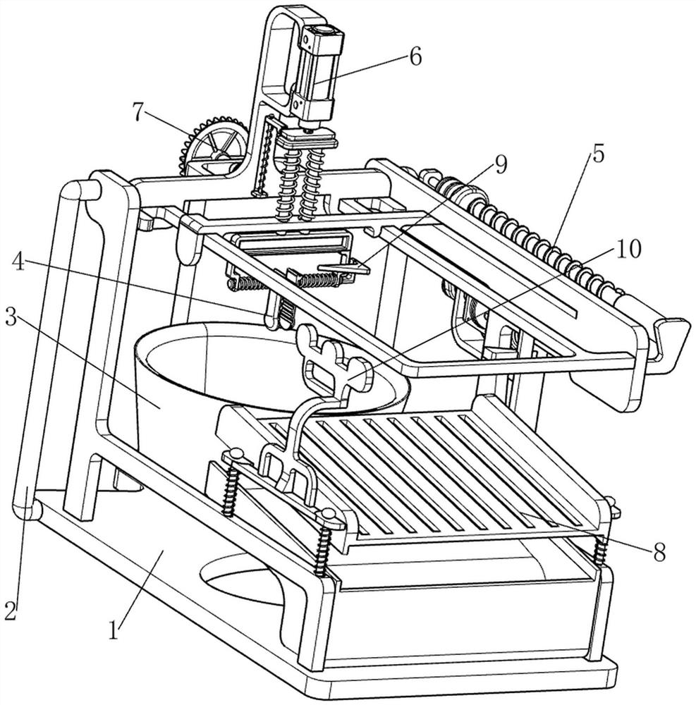
[0068] A dyeing device for jeans production, such as Figure 1-3As shown, it includes an underframe 1, a first support rod 2, a rotating frame 3, a clamp block 4, a feeding mechanism 5 and a pressing mechanism 6, and the left and right sides of the rear part of the underframe 1 are provided with first support rods 2. The rear part of the frame 1 is rotatably provided with a rotating frame 3, and a feeding mechanism 5 is connected between the two first support rods 2 and the bottom frame 1. The upper sliding type of the feeding mechanism 5 is provided with a down-pressing mechanism 6, and the lower part of the down-pressing mechanism 6 Both left and right sides are provided with clamping blocks 4 .

[0069] The worker first clamps the jeans through the clamping block 4, the worker pours the dye into the rotating frame 3, and then starts the feeding mechanism 5, the operation of the feeding mechanism 5 drives the operation of the pressing mechanism 6, and the operation of the pr...

Embodiment 2

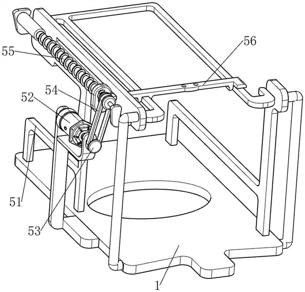
[0075] In a preferred embodiment of the present invention, as figure 1 with Figure 4-7 As shown, a reciprocating mechanism 7 is also included, and the reciprocating mechanism 7 includes a second transmission assembly 71, a second rotating shaft 72, a bevel gear set 73, a third rotating shaft 74, a shaft sleeve 75, an orientation gear 76, a rack 77, a third Spring 78, second sliding rod 79 and lower pressing block 710, the bottom frame 1 is equipped with a second rotating shaft 72 in a rotating manner at the rear, and a second transmission assembly 71 is connected between the lower side of the second rotating shaft 72 and the lower side of the rotating frame 3 , the second transmission assembly 71 is made up of two second pulleys and a second belt, one second pulley is connected to the lower side of the second rotating shaft 72, the other second pulley is connected to the lower side of the rotating frame 3, and the second belt is wound around the two sides. Between the two se...


PUM


Abstract

The invention relates to a dyeing device, in particular to a dyeing device for jeans production. According to the dyeing device for jeans production, jeans can be rapidly dyed, and meanwhile, the jeans can be dyed while being rotated, so that the jeans dyeing efficiency is effectively improved; and dye on the dyed jeans can be separated in a shaking mode, so that the labor intensity of workers can be relieved. The dyeing device for jeans production comprises a bottom frame, first supporting rods arranged on the two sides of the bottom frame, a rotating frame rotationally arranged on the bottom frame, a feeding mechanism connected between the two first supporting rods and the bottom frame, a pressing mechanism arranged on the feeding mechanism in a sliding manner, and clamping blocks arranged on the two sides of the lower portion of the pressing mechanism. According to the invention, the feeding mechanism is arranged and matched with the pressing mechanism, so that undyed jeans and dyed jeans can be conveyed in sequence.

Description

technical field [0001] The invention relates to a dyeing device, in particular to a dyeing device for jeans production. Background technique [0002] Jeans refer to a kind of jeans that are close to the body and look slender and slender when worn. Jeans, as one of the fashionable clothes today, have a wide range of applications. No matter what age group people have more or less jeans, because jeans The fabric is relatively soft, and its cut and style can effectively show the body line, so many people like this kind of clothing. Jeans can be divided into elastic and non-elastic. What kind of fabric is the jeans, before the promotion, the manufacturer needs to dye the jeans. The traditional dyeing method generally requires the workers to dye the jeans manually while rotating the dye, which will consume a lot of time and labor for the workers, thereby reducing Efficiency in dyeing jeans. [0003] Therefore, in view of the problems in the prior art mentioned above, it is neces...

Claims


Application Information

Patent Timeline
IPC IPC(8): D06B3/30D06B23/04D06B15/06D06B23/20
CPCD06B3/30D06B23/04D06B15/06D06B23/20
Inventor 陈富华
Owner 赣州辉之源制衣有限公司
Why Eureka
Try Eureka