Method and device for solving melting problem of frozen soil

A technology for frozen soil and control devices, which is applied in the fields of soil protection, construction, and infrastructure engineering, etc., and can solve problems such as inability to work at the same time, melting frozen soil, and limited construction time

Pending Publication Date: 2021-06-25
XIAN AIRCRAFT DESIGN INST OF AVIATION IND OF CHINA
View PDF5 Cites 0 Cited by
  • Summary
  • Abstract
  • Description
  • Claims
  • Application Information

AI Technical Summary

Problems solved by technology

[0005] In order to solve the above technical problems, this application provides a method and device for solving the thawing of permafrost, which can solve the technical problems that the construction time is limited and the work cannot be completed at the same time

Method used


Image

  • Method and device for solving melting problem of frozen soil
  • Method and device for solving melting problem of frozen soil
  • Method and device for solving melting problem of frozen soil

Examples


Embodiment 1

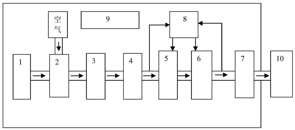
[0031] like figure 1 As shown, the present application provides a device for solving permafrost thawing, the device includes a generator 1, an air compressor 2, an air handling unit 3, an air storage tank 4, a pressure regulating device 5, a turbo cooler 6, and a ventilation pipe Road 7, control device 8, movable unit 9, permafrost soil 10, wherein:

[0032] The movable unit 9 is a platform for carrying equipment, and the movable unit 9 is equipped with a generator 1, an air compressor 2, an air handling unit 3, an air storage tank 4, a pressure regulating device 5, and a turbo cooler 6. On the ventilation pipeline 7 and the control device 8; the generator 1 and the air compressor 2 are connected through a circuit; Connected by pipelines; the output signal of the gas storage tank 4 and the input signal of the ventilation pipeline 7 are respectively connected with the input of the control device 8 through the signal line; the output of the control device 8 is connected with th...

Embodiment 2

[0044] The present application provides a method for solving permafrost thawing, the method is applied to the above-mentioned device for solving permafrost thawing, and the method includes:

[0045] Step 101: Determine the type of frozen soil body 10;

[0046] Step 102: According to the type of the permafrost soil mass 10, determine the blowing mode for blowing cold air from the ventilation pipeline 7;

[0047] Specifically, the types of the permafrost soil 10 include embankment slopes, pier pile foundations, and tunnels; the blowing modes include surface blowing, internal blowing, and both surface and internal blowing modes.

[0048] In practical applications, if the type of frozen soil 10 includes roadbed slopes and pier pile foundations, the blowing mode is surface blowing or internal blowing;

[0049] If the type of the frozen soil mass 10 is a tunnel, the blowing mode is surface blowing.

[0050] Step 103: Determine the cold air flow rate and cold air temperature of the...

Embodiment 3

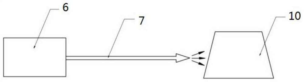
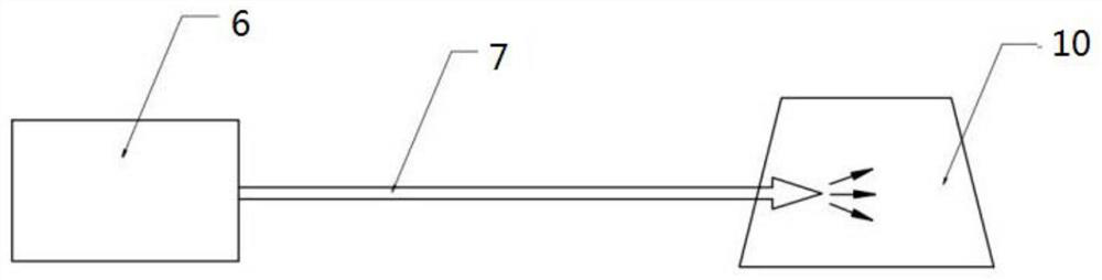
[0053] like figure 2 As shown, the embodiment of the present application takes the cold air provided by the cooling air source to directly act on the surface of the frozen soil body through the ventilation pipe to cool the frozen soil body as an example, for illustration:

[0054] Judging that the type of frozen soil 10 is the embankment slope, and determining that the blowing mode is surface blowing, the turbo cooler 6 will decompress and cool the compressed air with a certain temperature and pressure; The surface of the unthawed frozen soil mass 10 is cooled.


PUM


Abstract

The invention provides a method and device for solving a melting problem of frozen soil. The device comprises a generator 1, an air compressor 2, an air processing unit 3, an air storage tank 4, a pressure adjusting device 5, a turbine cooler 6, a ventilation pipeline 7, a control device 8, a movable unit 9 and a frozen soil body 10; the movable unit 9 is a platform for carrying equipment, and the generator 1, the air compressor 2, the air processing unit 3, the air storage tank 4, the pressure adjusting device 5, the turbine cooler 6, the ventilation pipeline 7 and the control device 8 are arranged on the movable unit 9; the generator 1 is connected with the air compressor 2 through a circuit; and the air compressor 2, the air processing unit 3, the air storage tank 4, the pressure adjusting device 5 and the turbine cooler 6 are sequentially connected through pipelines.

Description

technical field [0001] The invention relates to the technical field of road engineering health protection, in particular to a method and device for solving frozen soil melting. Background technique [0002] Permafrost is a kind of soil that is very sensitive to temperature and has unstable properties. This kind of soil has various types of soil (rock) with negative temperature and ice, and is also a complex substance with a porous structure. Frozen soil contains The four components are soil, water, ice, and air. Frozen soil is a widely existing geological condition, including permafrost, seasonal frozen soil and instantaneous frozen soil. The permafrost area accounts for 70% of the world's land area, and my country's permafrost area ranks third in the world. With the development and utilization of permafrost regions, a large number of engineering structures have been built in permafrost regions. In a large number of preliminary surveys and explorations, it was found that ...

Claims


Application Information

Patent Timeline
IPC IPC(8): E02D3/115
CPCE02D3/115
Inventor 禄宏志周景锋李欣
Owner XIAN AIRCRAFT DESIGN INST OF AVIATION IND OF CHINA
Why Eureka
Try Eureka