Elastic buffer casing and rigidity coefficient design method thereof

A technology of elastic cushioning and stiffness coefficient, applied in mechanical equipment, design optimization/simulation, engine components, etc., can solve problems such as impact damage of the rotor system and load-bearing casings, so as to prolong the action time, ensure safe and stable work, The effect of reducing impact force

Active Publication Date: 2021-06-25
AECC HUNAN AVIATION POWERPLANT RES INST
View PDF7 Cites 2 Cited by
  • Summary
  • Abstract
  • Description
  • Claims
  • Application Information

AI Technical Summary

Problems solved by technology

[0003] On the one hand, the present application provides an elastic buffer casing to solve the problem of rigid collision between the rotor system and the casing due to the disappearance of the oil film gap cause...

Method used


Image

  • Elastic buffer casing and rigidity coefficient design method thereof
  • Elastic buffer casing and rigidity coefficient design method thereof
  • Elastic buffer casing and rigidity coefficient design method thereof

Examples


Embodiment Construction

[0066] It should be noted that, in the case of no conflict, the embodiments in the present application and the features in the embodiments can be combined with each other. The present application will be described in detail below with reference to the accompanying drawings and embodiments.

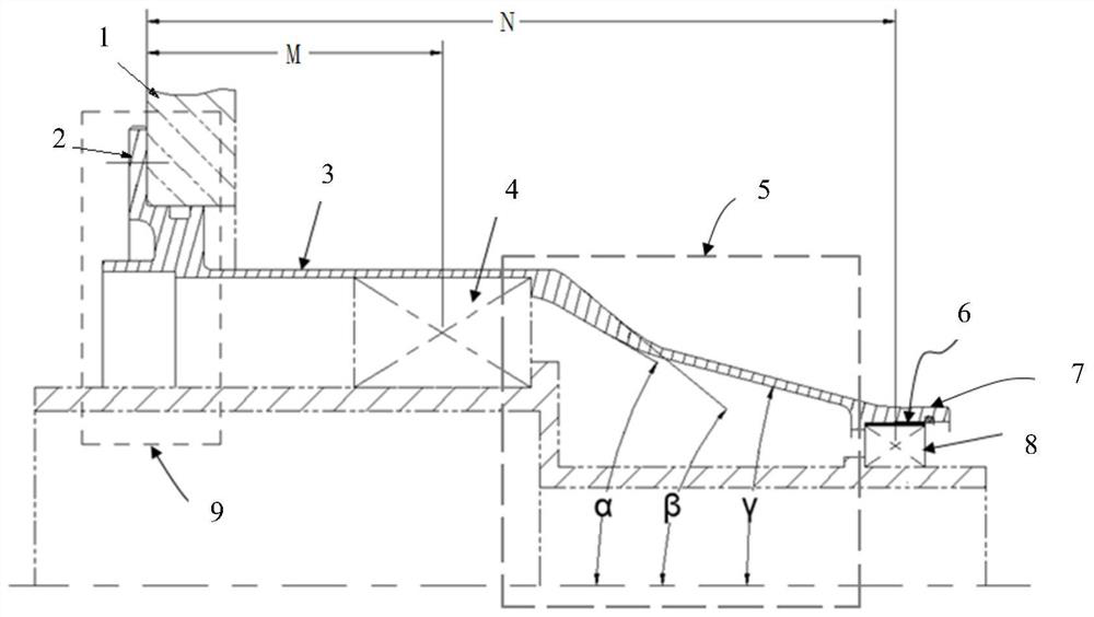
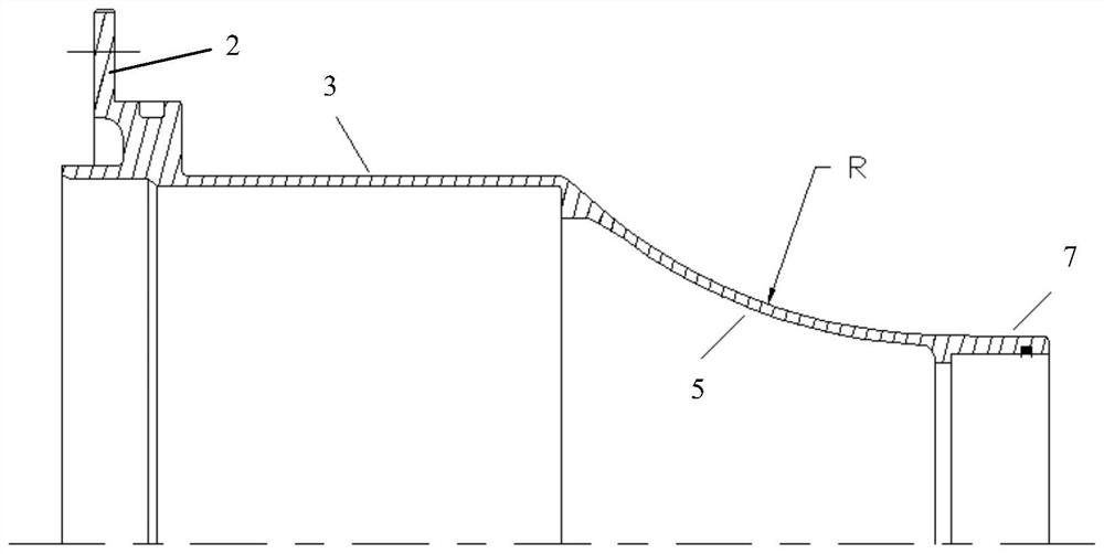
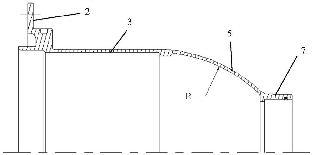
[0067] refer to figure 1 and figure 2 , The preferred embodiment of the present application provides an elastic buffer casing, the elastic buffer casing includes a flange section 9, a first bearing seat section 3, a transition section 5, and a second bearing seat section 7 in sequence along the axial direction ,

[0068] The flange section 9 is provided with a flange edge 2, and the flange edge 2 is fixedly connected with the outer casing 1 by bolts, thereby fixing one end of the elastic buffer casing on the outer casing 1;

[0069] The inner hole of the first bearing seat segment 3 matches the outer circle of the first bearing 4 installed on the power output shaft assembly;

[0070] ...


PUM


Abstract

The invention discloses an elastic buffer casing and a rigidity design method of the elastic buffer casing. The elastic buffer casing sequentially comprises a flange part section, a first bearing seat section, a transition section and a second bearing seat section in the axial direction, wherein the flange part section is provided with a flange edge, and the flange edge is fixedly connected with an outer casing through bolts, so that one end of the elastic buffer casing is fixed on the outer casing; an inner hole of the first bearing seat section is matched with an outer circle of a first bearing mounted on a power output shaft assembly; an inner hole of the second bearing seat section is matched with an outer circle of a second bearing mounted on the power output shaft assembly; and the diameter of the transition section is gradually transited from the diameter of the first bearing seat section to the diameter of the second bearing seat section in the axial direction. The action time of impact force is prolonged by reducing the rigidity coefficient of the elastic buffer casing, so that the effect of preventing a power turbine rotor system and the casing from being damaged by vibration impact is achieved, and safe and stable work of a whole aircraft engine is ensured.

Description

technical field [0001] The present application relates to the field of aviation turboshaft engines, in particular, to an elastic buffer casing and a method for designing its stiffness coefficient. Background technique [0002] At present, the turboshaft engine in the form of front output is used, and its power is transmitted from the power turbine to the output shaft through the power turbine shaft, so that the power turbine shaft is slender, has a large aspect ratio and is "soft", and has elastic supports at both ends. Generally, it is necessary to design extrusion oil film vibration reduction. When the engine rotor system experiences shock or large vibration, the oil film gap will disappear and cause rigid collision between the rotor system and the casing. If no protection is carried out, the rotor system and each bearing machine will be damaged. Cassette damage. For this reason, it is necessary to design an elastic buffer casing, which can play the role of flexible prote...

Claims


Application Information

Patent Timeline
IPC IPC(8): F01D25/24F01D25/04F01D25/16G06F30/17G06F30/23
CPCF01D25/24F01D25/243F01D25/04F01D25/16G06F30/17G06F30/23Y02E10/20
Inventor 陈冰蔡明先黄兴黄健李鑫
Owner AECC HUNAN AVIATION POWERPLANT RES INST
Why Eureka
Try Eureka