Vacuum joint and vacuum system

A vacuum system and vacuum technology, applied in the direction of pipes/pipe joints/pipe fittings, connections with fluid cut-off devices, engine components, etc., can solve the problems of cumbersome operation of vacuum joints and inability to effectively improve machining efficiency, and achieve structural Simple, easy to operate, solve the effect of cumbersome operation

Pending Publication Date: 2021-06-25
DONGXU OPTOELECTRONICS TECH CO LTD
View PDF0 Cites 0 Cited by
  • Summary
  • Abstract
  • Description
  • Claims
  • Application Information

AI Technical Summary

Problems solved by technology

However, the existing vacuum system has the problem that the operation of its vacuum joint is cumbersome and cannot effectively improve the efficiency of machining

Method used


Image

  • Vacuum joint and vacuum system
  • Vacuum joint and vacuum system
  • Vacuum joint and vacuum system

Examples


Embodiment Construction

[0021] Specific embodiments of the present invention will be described in detail below in conjunction with the accompanying drawings. It should be understood that the specific embodiments described here are only used to illustrate and explain the present invention, and are not intended to limit the present invention.

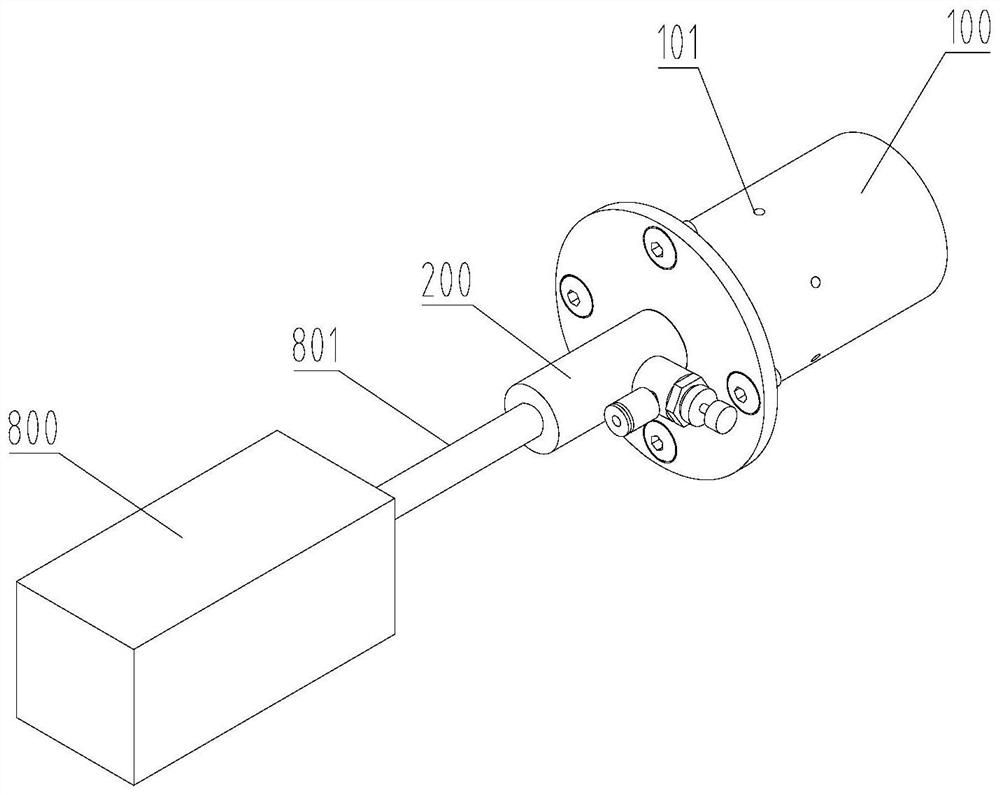
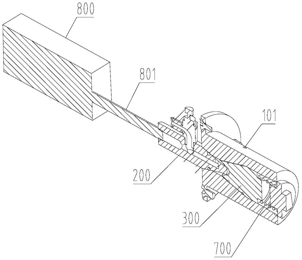
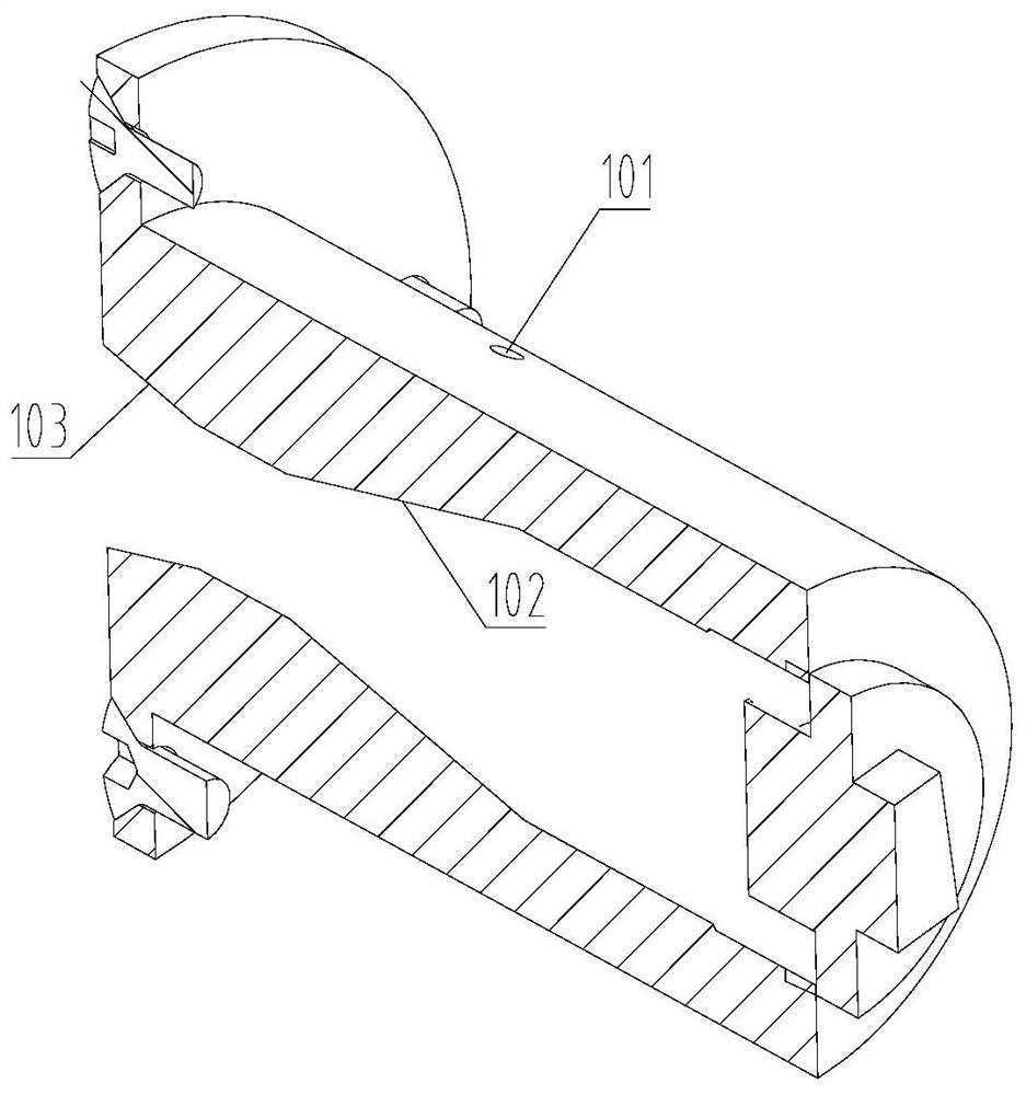
[0022] like Figure 1 to Figure 6 As shown, the vacuum joint of the present invention includes a joint base 100, a joint body 200 and a moving block 300; the joint base 100 has a chamber inside, and the joint base 100 is provided with a first through hole 101 communicating with the chamber; the joint body 200 One end is connected to an external vacuum source, and the other end extends into the chamber so that the chamber communicates with the vacuum source; the moving block 300 is movably arranged in the chamber along the first direction; wherein, the moving block 300 is configured to be able to move along the first direction The direction moves between the blo...


PUM


Abstract

The invention discloses a vacuum joint and a vacuum system. The vacuum joint comprises a joint seat, a joint body and a moving block, wherein a cavity is formed in the joint seat, and a first through hole communicating with the cavity is formed in the joint seat; one end of the joint body is connected with an external vacuum source, and the other end of the joint body extends into the cavity so as to enable the cavity to communicate with the vacuum source; the moving block is movably arranged in the cavity in the first direction; and the moving block is configured to be capable of moving between a shielding position and a conducting position in the first direction, at the shielding position, the moving block can disconnect the communication between the first through hole and the cavity, and at the conducting position, the moving block allows the first through hole to communicate with the cavity. The vacuum joint has the advantages of being simple and convenient to open and close and efficient.

Description

technical field [0001] The invention relates to the technical field of mechanical processing, in particular to a vacuum joint and a vacuum system. Background technique [0002] In mechanical processing operations (such as glass breaking, grinding and other deep processing operations), vacuum systems are widely used. The vacuum system uses vacuum connectors to vacuum the vacuum box to achieve functions such as adsorption. However, the existing vacuum system has the problem that the operation of the vacuum joint is cumbersome, and the efficiency of machining cannot be effectively improved. Contents of the invention [0003] The object of the present invention is to overcome the problems existing in the prior art, and provide a vacuum joint and a vacuum system. The vacuum joint has the advantages of simple and efficient operation for opening and closing. [0004] In order to achieve the above object, the present invention provides a vacuum joint on the one hand. The vacuum j...

Claims


Application Information

Patent Timeline
Patent Type & Authority Applications(China)
IPC IPC(8): F16L29/02F16K51/02
CPCF16K51/02F16L29/02
Inventor 廖民安李青陈发伟张旭李庆文
Owner DONGXU OPTOELECTRONICS TECH CO LTD
Why Eureka
Try Eureka