
A short-wave sky-wave propagation time difference positioning method based on straight-line distance difference

A linear distance and time difference positioning technology, applied in the field of radiation source positioning, can solve problems such as large errors and unusable positioning results, and achieve high positioning accuracy

Active Publication Date: 2022-04-29
WUHAN UNIV
View PDF5 Cites 0 Cited by
  • Summary
  • Abstract
  • Description
  • Claims
  • Application Information

AI Technical Summary

Problems solved by technology

Directly applying the existing algorithm to the location of the radiation source under the condition of short-wave sky-wave propagation will cause large errors, resulting in unusable positioning results

Method used


Image

  • A short-wave sky-wave propagation time difference positioning method based on straight-line distance difference
  • A short-wave sky-wave propagation time difference positioning method based on straight-line distance difference
  • A short-wave sky-wave propagation time difference positioning method based on straight-line distance difference

Examples


Embodiment Construction

[0090] In order to make the purpose, technical solutions and advantages of the embodiments of the present invention clearer, the technical solutions in the embodiments of the present invention will be clearly and completely described below in conjunction with the embodiments of the present invention. Obviously, the described embodiments are part of the present invention Examples, not all examples. Based on the embodiments of the present invention, all other embodiments obtained by persons of ordinary skill in the art without creative efforts fall within the protection scope of the present invention.

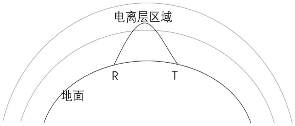
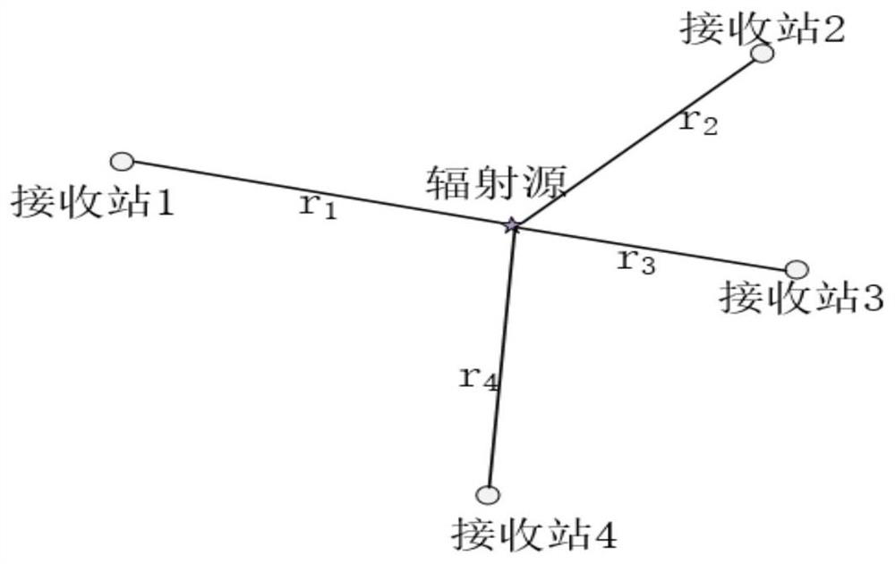
[0091] In the process of electromagnetic wave propagation, the propagation principle of direct wave and short wave is obviously different: short wave time difference positioning is different from direct wave time difference positioning. In the process of short wave propagation, due to ionospheric reflection propagation, the distance between the short wave propagation path and the ...


PUM


Abstract

The invention provides a short-wave sky-wave propagation time difference positioning method based on the linear distance difference. The present invention pre-acquires the conversion coefficient of the group path of the short wave emitted by the analog radiation source to the receiving station and the straight-line distance between the analog radiation source and the receiving station, and obtains the average conversion coefficient by taking the average value of the conversion coefficients obtained in advance; receiving the target radiation The short-wave signal of the source, and calculate the time difference data from the target radiation source to each receiving station by the generalized cross-correlation method; calculate the coordinates of the target radiation source according to the average conversion coefficient and the time difference data. The invention adds an ionospheric model to the traditional model, uses the actual time difference or path difference to convert into the straight-line distance difference in the traditional model through the average conversion coefficient, and then uses the traditional direct wave model to locate the target radiation source. The invention improves the positioning accuracy of the radiation source.

Description

technical field [0001] The invention relates to the field of radiation source positioning, in particular to a short-wave sky-wave propagation time difference positioning method based on straight-line distance difference. Background technique [0002] With the continuous development of electronic technology, modern electronic warfare increasingly presents a five-dimensional situation of sea, land, air, sky, and electromagnetic. Passive positioning technology is a passive positioning technology. Since the passive detection radar system itself does not emit electromagnetic waves, but receives electromagnetic signals from radiation sources in the detection airspace for positioning, it can also detect and track the enemy while concealing itself. Therefore, once the passive positioning is proposed, it has been widely concerned by all walks of life. [0003] There are two commonly used passive positioning technologies. One is to use a single moving platform to locate the target co...

Claims


Application Information

Patent Timeline
Patent Type & Authority Patents(China)
IPC IPC(8): G01S5/06
CPCG01S5/06
Inventor 周晨李琛吕明杰赵正予
Owner WUHAN UNIV
Learn More