Permanent magnet capable of axially adjusting uniform field

An axial adjustment, permanent magnet technology, applied in the direction of magnets, magnetic objects, permanent magnets, etc., can solve the problems of low field strength, increase in height, increase the volume of permanent magnets, etc., to reduce weight and cost, prevent excessive compensation, Compensate for the effect of end effects

Pending Publication Date: 2021-06-25
NORTHEAST DIANLI UNIVERSITY
View PDF2 Cites 0 Cited by
  • Summary
  • Abstract
  • Description
  • Claims
  • Application Information

AI Technical Summary

Problems solved by technology

[0003] The existing problem is that although the permanent magnet described in the patent CN 103860178A can effectively eliminate or reduce the eddy current and increase the signal-to-noise ratio, the overall weight is too large to reflect the advantages of portability, and the field strength

Method used


Image

  • Permanent magnet capable of axially adjusting uniform field
  • Permanent magnet capable of axially adjusting uniform field
  • Permanent magnet capable of axially adjusting uniform field

Examples


Example Embodiment

[0028] Embodiment 1, as a comparative example, the original height of the magnetic block of each layer magnetic ring is set to be 10mm in this embodiment, and the magnetic field intensity B 0 =1023.8mT, the uniformity is 8612ppm. Then the height of all the magnetic blocks in the ninth layer magnetic ring L1, the eighth layer magnetic ring L2, the second layer magnetic ring L8, and the first layer magnetic ring L9 are raised to 14mm, and the uniformity of the permanent magnet is 5259ppm. After the height of all the magnetic blocks in the seven-layer magnetic ring L3 and the third-layer magnetic ring L7 are increased to 14mm, the uniformity of the permanent magnet is 5899ppm, but there is an overcompensation for the uniformity.

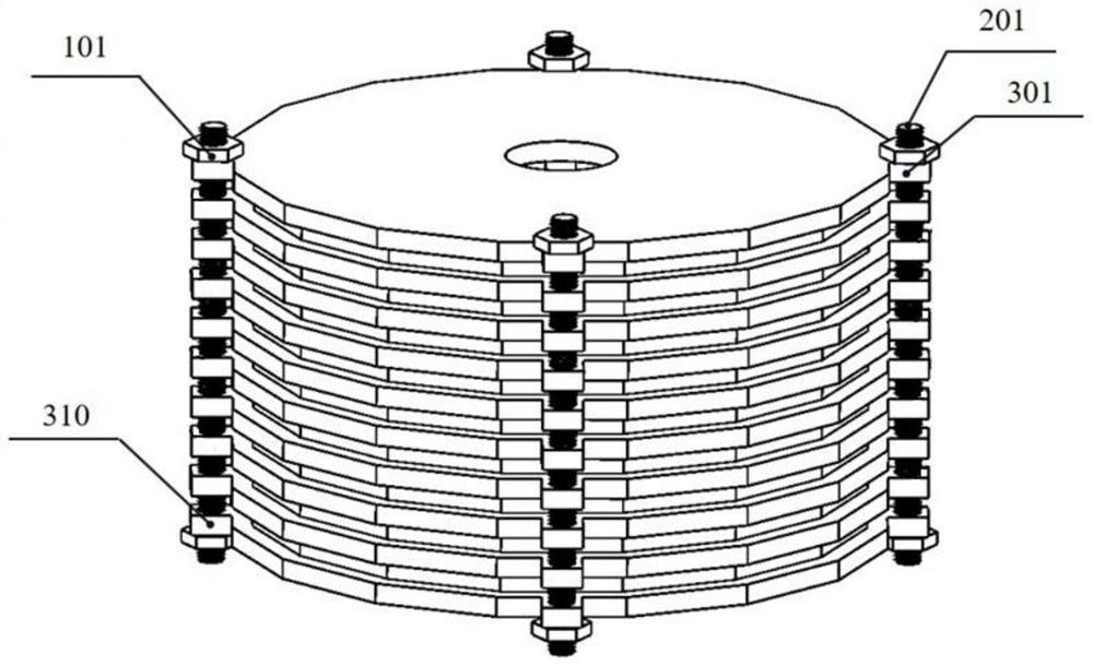
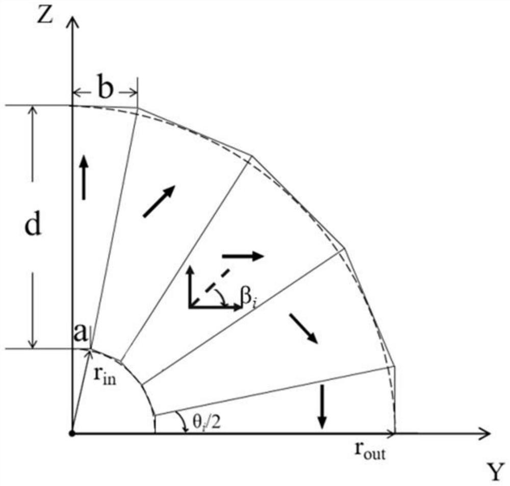
[0029] see Figure 1~5 , Example 2, such as figure 1 As shown, the present embodiment is a permanent magnet for axially adjusting a uniform field, which includes a base plate and a magnetic ring, the base plate is ring-shaped, and the number of layers...

Example Embodiment

[0054] Comparing Embodiment 2 with Embodiment 1, with respect to the ninth-layer magnetic ring L1, the eighth-layer magnetic ring L2, the seventh-layer magnetic ring L3, the third-layer magnetic ring L7, and the second-layer magnetic ring of Embodiment 1, The method of raising the height of all magnetic blocks in the ring L8 and the first layer magnetic ring L9 improves the uniformity by 31.5%; this embodiment improves the uniformity by 88.5%, and compared with the ninth layer magnetic ring L1 and the eighth layer The method of increasing the height of all magnetic blocks in the magnetic ring L2, the seventh magnetic ring L3, the third magnetic ring L7, the second magnetic ring L8, and the first magnetic ring L9 uses 50.2% less material.

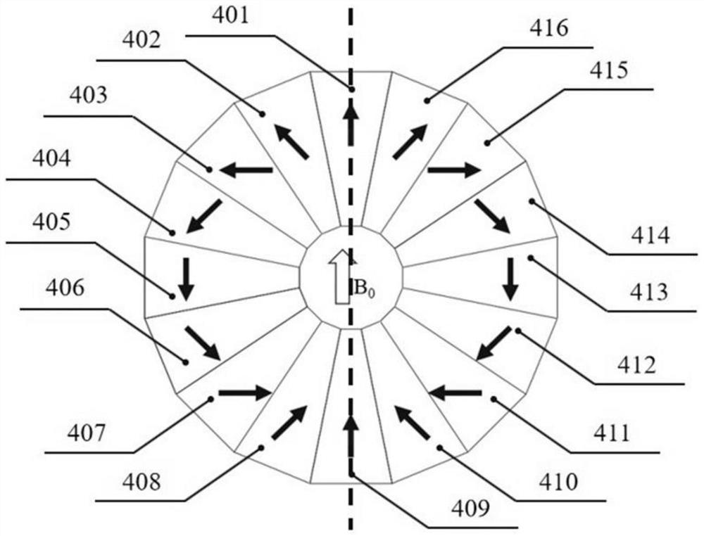
[0055] The number of magnetic ring layers in this embodiment 2 is N=9, the number of magnetic blocks in each magnetic ring is M=16, the structure size is Φ142×240 mm, the structure is hollow inside, and the middle aperture is Φ60 mm. Compare...


PUM


Abstract

The invention relates to a permanent magnet capable of axially adjusting a uniform field, which is characterized in that the permanent magnet comprises base plates and magnetic rings, the base plate is annular, N + 1 layers of base plates and N layers of magnetic rings are alternately overlapped from bottom to top, the first layer of base plate is used as a bottom plate and is positioned at the lowest part of the magnetic ring, and the N + 1 layer of base plate is used as a cover plate and is positioned at the uppermost part of the magnetic ring; the N + 1 layers of base plates are fixedly connected in sequence from bottom to top, so that the N layers of magnetic rings are stacked to form a column type permanent magnet with an internal cavity, the internal cavity of the column type permanent magnet is a uniform magnetic field, and N>2 . According to the structure, only the heights of part of the magnetic blocks need to be finely adjusted, less magnetic materials are used, the weight and manufacturing cost of the permanent magnet structure are reduced, and the phenomenon of excessive compensation is prevented. Therefore, the permanent magnet provided by the invention can generate a magnetic field with high magnetic field intensity and high uniformity in a miniaturized instrument.

Description

technical field [0001] The invention belongs to the field of permanent magnets, in particular to the technical field of permanent magnets used for nuclear magnetic resonance, and is a permanent magnet for axially adjusting a uniform field. Background technique [0002] Patent CN 103860178A discloses a permanent magnet used in an MRI apparatus, which contains an eddy current disk inside, which can better eliminate or reduce eddy current, has a high signal-to-noise ratio, and has a clearer image. The document "QiaoyanChen, GuangcaiZhang, Yajie Xu, et al.Design and simulation of a multilayer Halbachmagnet for NMR.2015, 45(3):134-141." discloses a method to calculate the height of all magnetic blocks contained in the magnetic rings at both ends. Increase, the method of reducing the height of all the magnetic blocks contained in the central magnetic ring to compensate for the end effect. [0003] The existing problem is that although the permanent magnet described in the patent ...

Claims


Application Information

Patent Timeline
IPC IPC(8): H01F7/02G01R33/383
CPCH01F7/0278H01F7/0284H01F7/0221G01R33/383G01R33/3802
Inventor 姜文娟李俊洲生迪迪
Owner NORTHEAST DIANLI UNIVERSITY
Why Eureka
Try Eureka