Control method of fuel cell system

The technology of a fuel cell system and control method is applied in the direction of fuel cells, fuel cell additives, power system fuel cells, etc., and can solve the problems of excessive water content increase, fuel cell stack output power reduction, and damage to fuel cell stack life and other problems, to achieve the effect of controllable amplitude and controllable excessive increase of water content

Active Publication Date: 2021-06-25
亿华通动力科技有限公司
View PDF9 Cites 4 Cited by
  • Summary
  • Abstract
  • Description
  • Claims
  • Application Information

AI Technical Summary

Problems solved by technology

The increase of the output current of the fuel cell will lead to a synchronous increase in the water content generated by the electrochemical reaction in the fuel cell stack, and the excessive increase of the water content inside the fuel cell stack will in turn lead to a decrease in the output power of the fuel cell stack and damage the fuel cell power. heap lifetime

Method used


Image

  • Control method of fuel cell system
  • Control method of fuel cell system

Examples


Embodiment Construction

[0033] In order to make the technical problems solved by the present invention, the technical solutions adopted and the technical effects achieved clearer, the technical solutions of the embodiments of the present invention will be further described in detail below in conjunction with the accompanying drawings. Obviously, the described embodiments are only the technical solutions of the present invention. Some, but not all, embodiments. Based on the embodiments of the present invention, all other embodiments obtained by those skilled in the art without making creative efforts belong to the protection scope of the present invention.

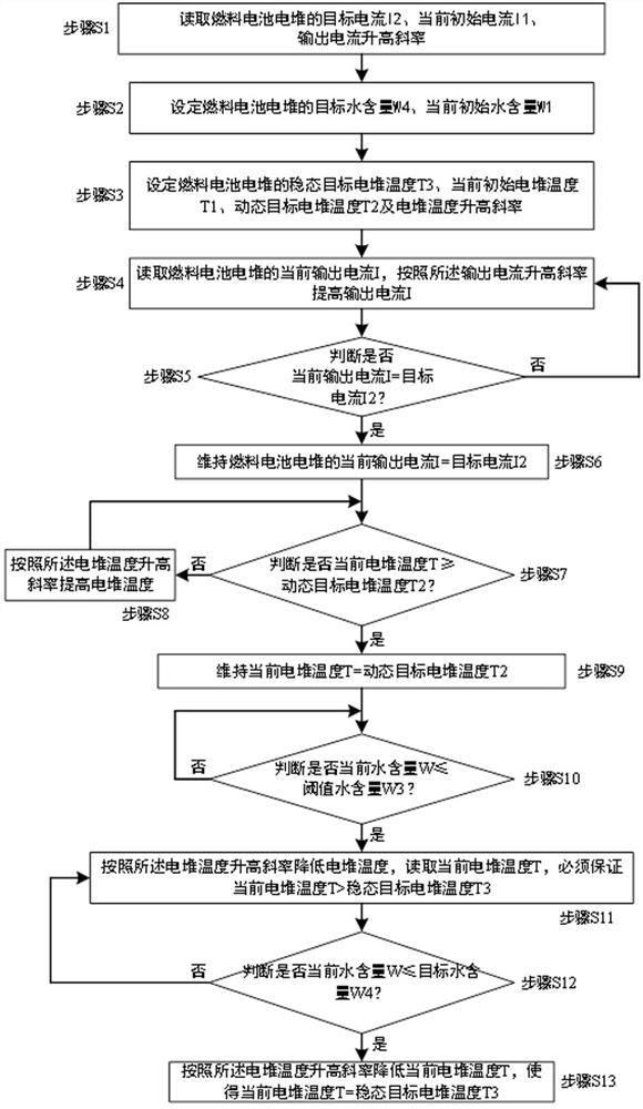
[0034] Such as figure 1 As shown, this embodiment provides a control method for a fuel cell system, including the following steps:

[0035] Step S1: the control flow starts;

[0036] Step S2: Read the target current I2 of the fuel cell stack, read the current initial current I1 of the fuel cell stack, and set the output current rising slope dI / d...


PUM


Abstract

The invention discloses a control method of a fuel cell system, and belongs to the field of fuel cells. According to the control method of the fuel cell system provided by the invention, the temperature of the fuel cell stack is controlled by controlling the current of the fuel cell stack, and finally the water content is controlled. According to the control method of the fuel cell system, in a period of time after the output current of the fuel cell system is rapidly increased and the output current is stabilized, the excessive increase amplitude of the water content in the fuel cell stack is controllable, and the water content can be rapidly recovered to the balanced water content corresponding to the output current.

Description

technical field [0001] The invention relates to the field of fuel cells, in particular to a control method for a fuel cell system. Background technique [0002] A fuel cell is an electrochemical reaction device that generates water by the reaction of hydrogen and oxygen in two half-electrodes, converting chemical energy into electrical energy and converting it into thermal energy with efficiency loss. [0003] The fuel cell stack is formed by connecting multiple fuel cell sheets in series in a repeating manner of negative electrode-positive electrode-negative electrode-positive electrode, and two adjacent fuel cell sheets are separated by bipolar plates. A hydrogen supply channel is formed on one side of the bipolar plate and is in contact with the hydrogen reaction electrode, an oxygen (air) supply channel is formed on the other side of the bipolar plate and is in contact with the oxygen reaction electrode, and is formed in the middle of the bipolar plate There are coolant...

Claims


Application Information

Patent Timeline
IPC IPC(8): H01M8/0432H01M8/04492H01M8/04537H01M8/04701H01M8/04828H01M8/04858H01M8/04992H01M8/04291
CPCH01M8/04291H01M8/04358H01M8/04492H01M8/04589H01M8/04723H01M8/04843H01M8/0491H01M8/04992H01M2250/20Y02E60/50
Inventor 刘秀会洪坡
Owner 亿华通动力科技有限公司
Why Eureka
Try Eureka