
Compressor motor rotor structure capable of improving heat dissipation effect and heat dissipation method

A technology of motor rotor and heat dissipation effect, applied in the direction of magnetic circuit shape/style/structure, magnetic circuit rotating parts, etc., can solve problems such as weak heat dissipation effect, demagnetization of permanent magnets, and the risk of demagnetization of accelerated magnetic steel 10, so as to reduce The effect of high temperature demagnetization risk, reduction of flux leakage, and improvement of motor efficiency

Pending Publication Date: 2021-06-25
比泽尔旋转压缩机(江苏)有限公司
View PDF3 Cites 0 Cited by
  • Summary
  • Abstract
  • Description
  • Claims
  • Application Information

AI Technical Summary

Problems solved by technology

[0003] But still to the variable-frequency motor with large calorific value, because the flow hole 7 is far away from the magnetic steel 10, the heat dissipation effect is not strong. In addition, the high temperature causes the main reason for the demagnetization of the permanent magnet. The risk of demagnetization, therefore, there is an urgent need for a compressor motor rotor structure and a heat dissipation method to improve the heat dissipation effect to solve the above problems

Method used


Image

  • Compressor motor rotor structure capable of improving heat dissipation effect and heat dissipation method
  • Compressor motor rotor structure capable of improving heat dissipation effect and heat dissipation method
  • Compressor motor rotor structure capable of improving heat dissipation effect and heat dissipation method

Examples


Embodiment Construction

[0034] In order to make the technical means, creative features, goals and effects achieved by the present invention easy to understand, the present invention will be further described below in conjunction with specific embodiments.

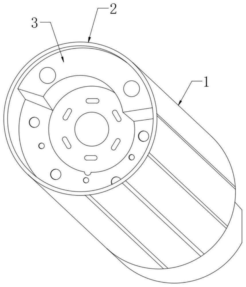
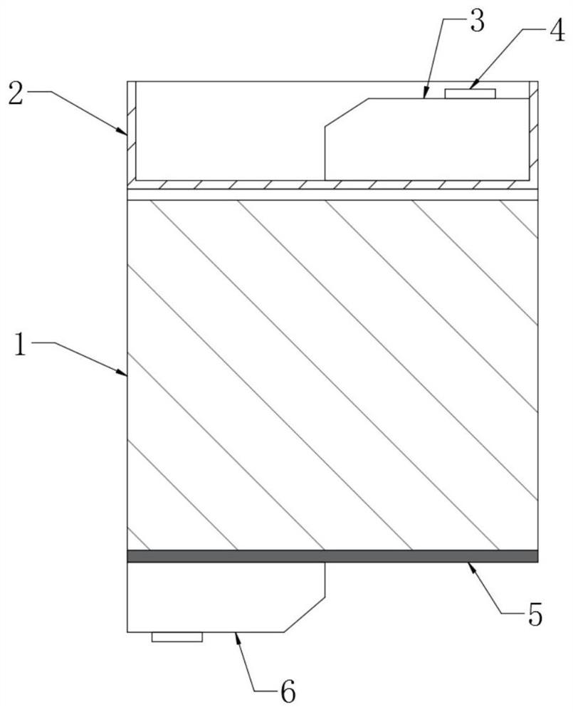
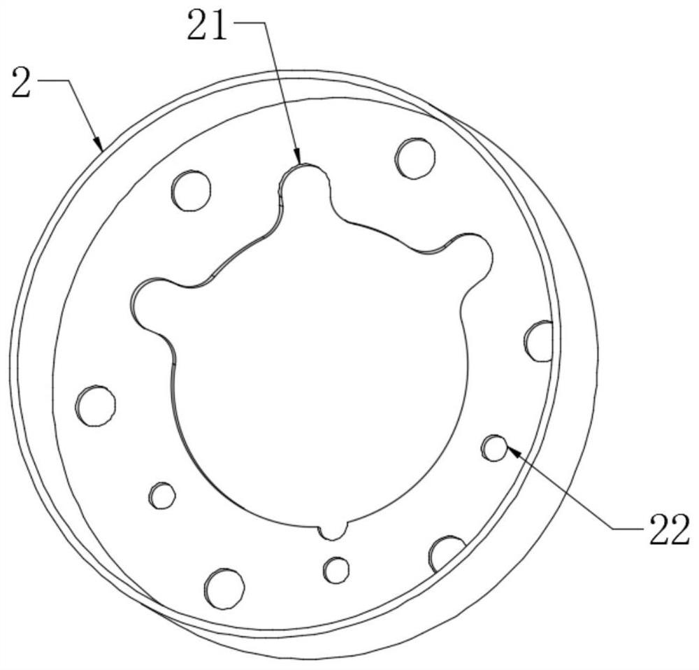
[0035] see Figure 1-Figure 8 , the present invention provides a technical solution: a compressor motor rotor structure and heat dissipation method for improving heat dissipation, including a rotor core 1, an oil baffle 2 and a baffle 5, and the oil baffle 2 is arranged on the rotor core 1 At one end, the baffle plate 5 is arranged on the other end of the rotor core 1, and a plurality of V-shaped magnetic steels 12 are arranged at equal intervals on the rotor core 1, and flow grooves 11 are opened between adjacent V-shaped magnetic steels 12 to solve the problem of It solves the problem that the heat dissipation of the magnetic steel part of the rotor of the compressor motor in the past is not sufficient and reasonable.

[0036] Specific heat dis...


PUM


Abstract

The invention provides a compressor motor rotor structure capable of improving a heat dissipation effect and a heat dissipation method. The compressor motor rotor structure comprises a rotor iron core, an oil baffle plate and a baffle plate, wherein the oil baffle plate is arranged at one end of the rotor iron core, the baffle plate is arranged at the other end of the rotor iron core, a plurality of V-shaped magnetic steels are arranged on the rotor iron core at equal intervals in a penetrating manner, through-flow grooves are formed between adjacent V-shaped magnetic steels, The compressor motor rotor structure solves a problem that heat dissipation of a magnetic steel part of a conventional compressor motor rotor is not sufficient and reasonable enough, is reasonable in structure, and enables a smooth heat dissipation refrigerant to pass through a part, with the maximum heating value, of the magnetic steel part by forming the flow grooves in the magnetic steel part, and thereby performances of a motor and a compressor are improved; in addition, the baffle plate and the oil baffle plate are improved, so the circulation effect of the refrigerant is enhanced, and the heat dissipation effect is enhanced.

Description

technical field [0001] The invention relates to a compressor motor rotor structure and a heat dissipation method for improving heat dissipation effect, and relates to the field of DC brushless motors, permanent magnet synchronous motors, and rotors in variable frequency compressor compressors. Background technique [0002] In the built-in permanent magnet motor, the heat dissipation of the compressor motor has always been a difficult point in the compressor technology. The motor is the main source of heat for the compressor. Now many companies add flow holes to the shape of the stator and rotor of the compressor motor. , so that the pump body of the compressor can be discharged smoothly, and the heat of the motor can be taken away. The existing rotor core structure is designed as Figure 8 , Reference numeral 7 is a flow hole, the magnetic steel 10 is between the two baffles 9, and part of the rotor heat can be taken away through the flow hole 7. [0003] But still to the v...

Claims


Application Information

Patent Timeline
Patent Type & Authority Applications(China)
IPC IPC(8): H02K1/32H02K1/27
CPCH02K1/32H02K1/27
Inventor 尹伟锋张青王小平
Owner 比泽尔旋转压缩机(江苏)有限公司
Learn More