
System for cutting strips using helical knives and corresponding cutting method

A cutting system and strip technology, used in household appliances, other household appliances, applications, etc., can solve problems such as high energy, high cutting force, and limited throughput of cutters

Active Publication Date: 2021-06-25
MICHELIN & CO (CIE GEN DES ESTAB MICHELIN)
View PDF10 Cites 0 Cited by
  • Summary
  • Abstract
  • Description
  • Claims
  • Application Information

AI Technical Summary

Problems solved by technology

Therefore, the production throughput of the cutter will be limited
[0006] In addition, such cutters usually require high cutting forces, which consume a lot of energy
[0007] Finally, due to the overall size and mechanical feasibility, the range of cutting angles available with this cutter will be limited

Method used


Image

  • System for cutting strips using helical knives and corresponding cutting method
  • System for cutting strips using helical knives and corresponding cutting method
  • System for cutting strips using helical knives and corresponding cutting method

Examples


Embodiment Construction

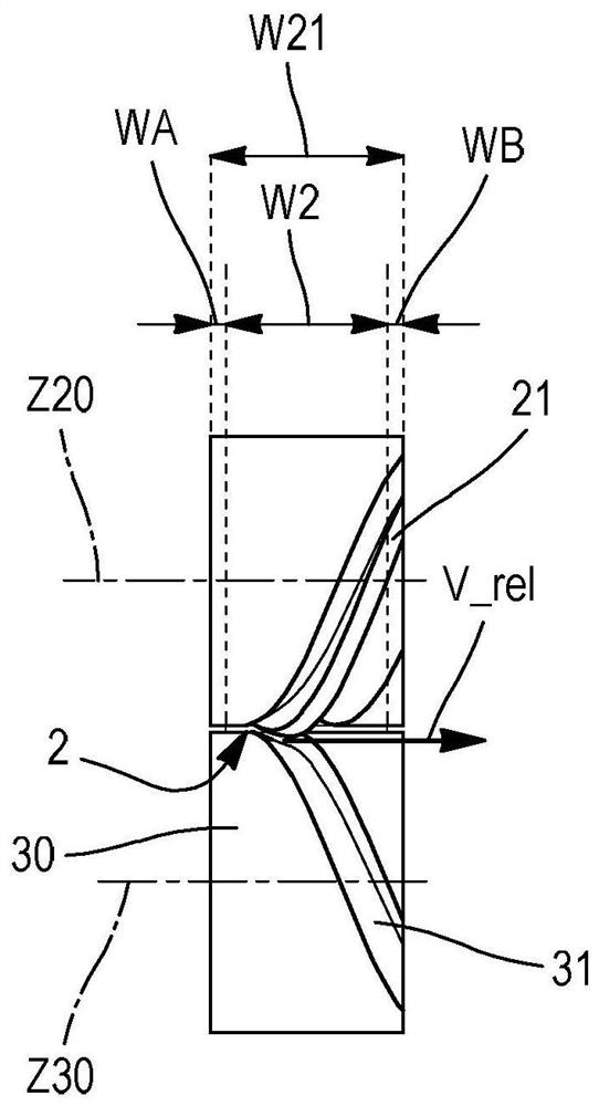
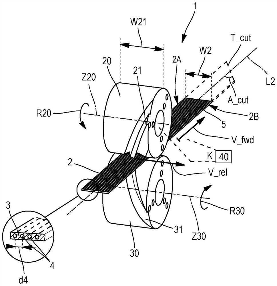
[0036] The present invention relates to a cutting system 1 aimed at cutting a strip 2 called "continuous strip" 2.

[0037] The continuous strip 2 extends in the longitudinal direction in a direction called "longitudinal direction" L2 and extends in the width direction W2 between the first edge 2a and the second edge 2b.

[0038] In image 3 As can be seen from the continuous strip 2, the continuous strip 2 preferably consists of a "zero-degree belt layer" formed by at least one rubber layer 3, the rubber layer 3, which extends parallel to each other on the longitudinal direction L2 of the continuous strip 2. The reinforcing cord 4 (which is preferably metal) is enhanced.

[0039] The reinforcing cord 4 can be multi-wire stocks, i.e., each of the components of the interleaving line stock, or preferably a single strand, i.e., each of which is formed only by one integrated strand.

[0040]The reinforcing cord 4 can be made of any material that is not so sensitive to elongation compar...


PUM


Abstract

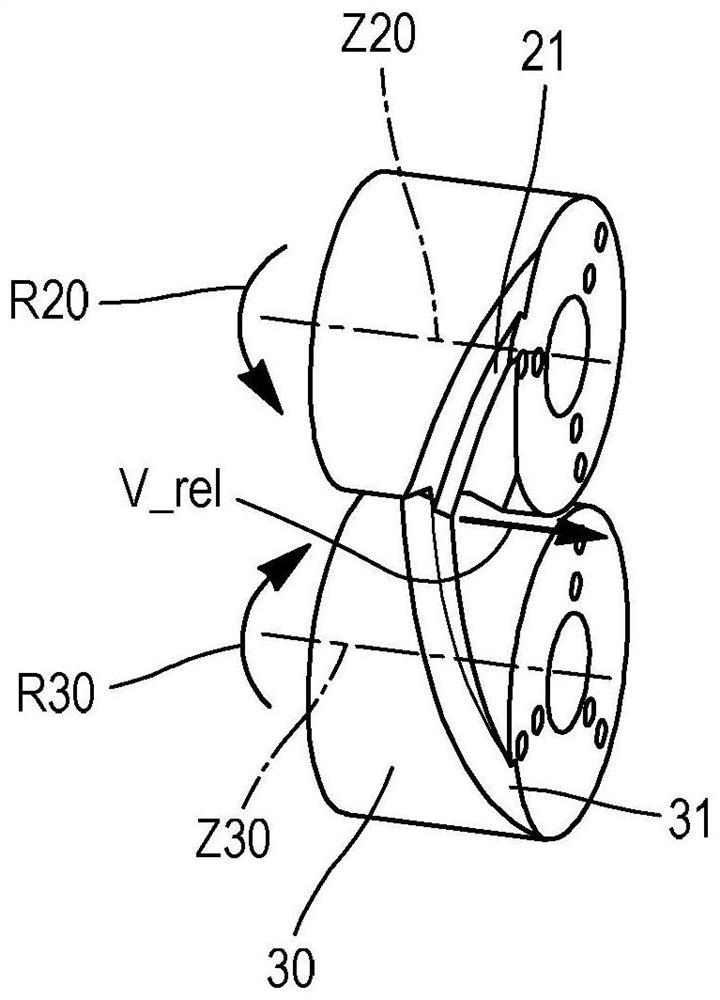
The invention relates to a cutting system (1) for cutting into strips (5) a continuous strip (2) which extends lengthwise in a longitudinal direction (L2) and widthwise (W2) between a first edge (2A) and a second edge (2B), said cutting system comprising a drive device (10) which imparts on the continuous strip (2) a feed speed (V_fwd), a first cutting roller (20) and a second cutting roller (30) which are counter-rotating and cooperate to cut the continuous strip (2) across its full width (W2), said first cutting roller (20) being provided for this purpose with a first helical blade (21) and being driven in rotation (R20), and a variable synchronizer (40), which makes it possible to select and modify the synchronization ratio (K) between the rotational speed (R20) of the first cutting roller and the non-zero feed speed (V_fwd) of the continuous strip in such a way as to be able to adjust the so-called cutting angle (A_cut) according to which the cross-section of the continuous strip (2) is oriented with respect to the longitudinal direction (L2) of said continuous strip (2).

Description

Technical field [0001] The present invention relates to the fabrication of the strip by cutting the initial continuous strip, and more particularly to the application of the strip in this manner in the manufacturing tire (especially a pumped tire). Background technique [0002] Many systems have been known to make the enhanced curtain layer, which cut the strip, and then placed on the edges on the edges on the assembly support (e.g., conveyors or drums) to make the edges of a series of strip to form a desired strip. Enhance the curtain layer. [0003] Typically, the strip is cut into a certain length by a cutter having a gate type linear blade, wherein the blade cuts a continuous strip in the entire width of the continuous strip. [0004] Since the blade must cover the entire width of the continuous strip (including generating a lateral), this cutter sometimes looks more cumbersome. [0005] Further, the use of such a cutter must stop the continuous strip in each cut to prevent t...

Claims


Application Information

Patent Timeline
Patent Type & Authority Applications(China)
IPC IPC(8): B29D30/46B26D1/153B26D3/00
CPCB29D30/46B26D3/003B26D1/265B26D1/285B29D30/28B29D30/3042
Inventor F·普拉洛C·贝萨克C·迪布瓦O·福克斯
Owner MICHELIN & CO (CIE GEN DES ESTAB MICHELIN)
Learn More