Eureka AIR delivers breakthrough ideas for toughest innovation challenges, trusted by R&D personnel around the world.

A high-efficiency corn cob device

A high-efficiency technology for corn crushing, used in threshing equipment, agriculture, applications, etc., can solve the problems of unable to guarantee stable core crushing and conveying, relying on spring consistency, unable to guarantee simultaneous clamping and positioning, etc.

Active Publication Date: 2022-04-12
NANJING AGRI MECHANIZATION INST MIN OF AGRI
View PDF9 Cites 0 Cited by
  • Summary
  • Abstract
  • Description
  • Claims
  • Application Information

AI Technical Summary

Problems solved by technology

[0004] After analysis, it was found that the causes of the damage were as follows: 1) The clamping mechanism only relied on the elastic deformation of the elastic roller to adapt to corn ears of different diameters, and the difference in diameter of different parts on the same ear, the clamping mechanism could not provide stability for the corn ear. The continuous clamping force will damage the corn kernels, and it is difficult to ensure the stability of the corn cobs; 2) The cob drill combined with the circular drill and the central twist drill is difficult to adapt to the corn cobs of different sizes, which will damage the corn Grain; 3) The clamping mechanism and the positioning mechanism are two separate mechanisms. The length of corn ears ranges from more than ten centimeters to more than thirty centimeters. For shorter corn ears, it is impossible to guarantee simultaneous clamping and positioning, so there is no guarantee Core stabilization and conveying
The positioning mechanism composed of three spring expanders, the three springs do not have a mutual coordination mechanism, rely too much on the consistency of the elastic coefficients of the springs, the positioning accuracy cannot be guaranteed, and with the increase in the number of stretches, the positioning error will increase after the spring fatigue Continue to increase

Method used


Image

  • A high-efficiency corn cob device
  • A high-efficiency corn cob device
  • A high-efficiency corn cob device

Examples


Embodiment 1

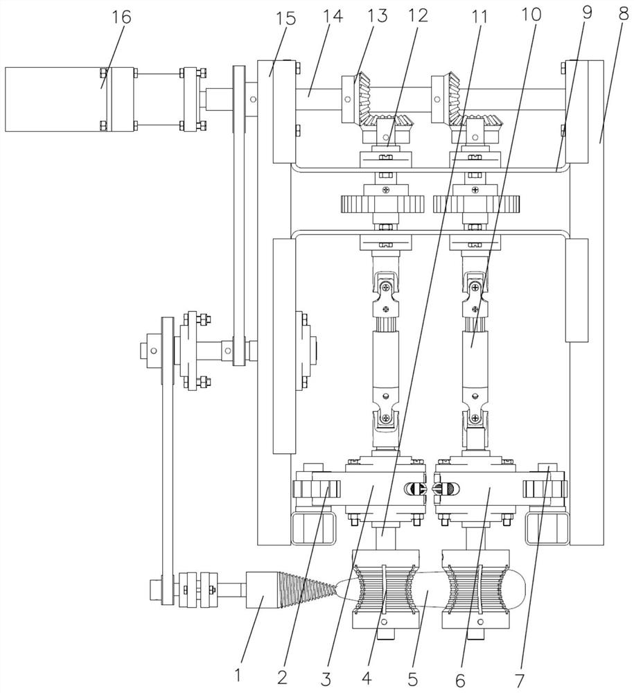
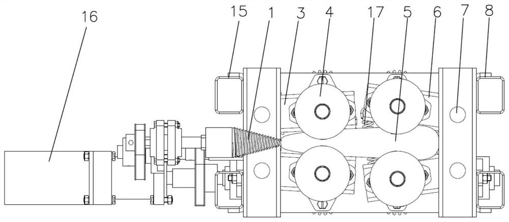
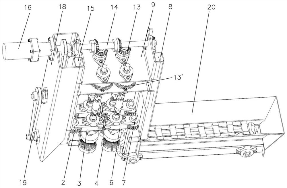
[0025] The high-efficiency corn cob device of the present embodiment is as Figure 1 to Figure 4 Shown, comprise front and rear struts 15,8 that are fixedly connected with the frame, the bottom of front and rear struts 15,8 are respectively hinged by vertical pin 7 and stretch forward left and right hinged plates 6 and stretch left and right. The right hinged plate 3, the hinges of the forward left and right hinged plates 6 and the rearward stretched left and right hinged plates 3 are respectively fixedly connected with the corresponding synchronous meshing gears 2, and the forward left and right hinged plates 6 and the rear The cantilever ends of the left and right hinged plates 3 are respectively connected with the corresponding extension springs 17, so there is a tendency to move closer to each other. Each hinge plate 3 , 6 respectively supports the saddle roller 4 driven by the driving shaft 14 through the universal joint 10 . Specifically, the horizontal drive shaft 14 d...


PUM


Abstract

The invention relates to a corn cob breaking device, which belongs to the technical field of agricultural machinery. The device comprises forward left and right hinged plates and rearward left and right hinged plates hinged on the frame, and the hinges of the forward left and right hinged plates and the rearward left and right hinged They are respectively fixedly connected with the corresponding synchronous meshing gears, and the cantilever ends of the left and right hinged plates extending forward and the left and right hinged plates extending backward are respectively connected with corresponding extension springs; each hinged plate respectively supports the driving shaft through the ten thousand The saddle rollers driven by knuckles form a left and right pair of front and rear saddle rollers floating clamping and conveying mechanism; the output end of the floating clamping conveying mechanism is equipped with a split cone whose rotation axis is aligned with the conveying centerline , the taper thread is formed on the cone body of the split cone. The invention can realize high-efficiency broken cores, effectively avoid damage to corn kernels, and creates ideal conditions for ensuring corn threshing quality and reducing threshing damage.

Description

technical field [0001] The invention relates to a corn threshing pretreatment device, in particular to a corn cob breaking device, which belongs to the technical field of agricultural machinery. Background technique [0002] At present, threshing and direct harvesting of high-humidity corn grains has become the development trend of corn mechanized harvesting, and the key link of direct grain harvesting is threshing. The threshing device is the core component to realize direct grain harvesting. It has an important influence on the operating performance such as efficiency and cleaning rate. Due to the mutual support between the kernels on the corn ear, it is difficult for the corn kernels to be detached from the mandrel, and as the moisture content of the corn ear increases, the corn kernels are fuller, and the mutual extrusion and support are more severe. It leads to more difficult threshing, greater damage and lower removal rate. [0003] It can be seen from the search tha...

Claims


Application Information

Patent Timeline
Patent Type & Authority Patents(China)
IPC IPC(8): A01F11/06A01F12/00
CPCA01F11/06A01F12/00
Inventor 王刚吴崇友张敏汤庆吴俊江涛金梅蒋兰梁苏宁
Owner NANJING AGRI MECHANIZATION INST MIN OF AGRI
Why Eureka
Eureka Blog
Learn More