
Workpiece shape correcting method and workpiece shape correcting device

A technology for shape correction and workpiece, applied in the field of workpiece shape correction method and workpiece shape correction device, can solve the problems of shape correction processing of metal processing parts, easily damaged hub, and no measurement, so as to improve shape correction accuracy, avoid damage, The effect of improving accuracy and efficiency

Active Publication Date: 2021-06-29
NINGBO INST OF MATERIALS TECH & ENG CHINESE ACADEMY OF SCI
View PDF10 Cites 1 Cited by
  • Summary
  • Abstract
  • Description
  • Claims
  • Application Information

AI Technical Summary

Problems solved by technology

[0004] However, in the wheel hub shape correction scheme in the prior art, on the one hand, the deformation area and deformation amount of the wheel hub cannot be accurately obtained before the wheel hub shape adjustment, that is, the deformation area and deformation amount of the wheel hub are usually not measured, and It is to directly correct the shape of the hub, which makes the hub shape inaccurate. On the other hand, in the prior art, the hub shape is only calibrated for the axial deformation of the hub, and cannot be calibrated for the radial deformation of the hub. , the scope of application is narrow, and the contact mechanical pressure is used to correct the shape, which is easy to cause damage to the hub. For example, in the above-mentioned CN210547606U, the pressure is forced to be applied along the axial direction of the hub by tapered rollers. Three tapered rollers, the range of activity of the tapered rollers determines the size of the shaping hub, and the cone angle of the tapered rollers limits the type of the shaping hub, so that the device can only be used for shaping the specific hub
[0005] In addition, in the wheel hub shape correction scheme in the prior art, no shape correction treatment is performed on the metal processing parts (that is, the metal plate parts before the wheel hub is formed), which affects the forming quality of the wheel hub, and increases the difficulty and cost of the subsequent wheel hub shape correction.

Method used


Image

  • Workpiece shape correcting method and workpiece shape correcting device
  • Workpiece shape correcting method and workpiece shape correcting device
  • Workpiece shape correcting method and workpiece shape correcting device

Examples


Embodiment 1

[0070] When the workpiece to be calibrated is a metal plate to be processed, the measurement mechanism includes a first-line laser, a measurement manipulator and a measurement control module. The measurement manipulator is connected to the first-line laser, and the first-line laser and the measurement manipulator are further connected to the measurement control module. , the first-line laser is used to measure the metal plate to be processed, the measuring manipulator is used to drive the first-line laser to move, the measurement control module is used to control the movement of the measuring manipulator and calculate the metal plate to be processed according to the data obtained by the first-line laser measurement The difference between the piece and the reference sheet metal piece is used to obtain the machining allowance of the sheet metal piece to be processed. During implementation, the metal sheet to be processed is placed on the workbench, and the measurement control mod...

Embodiment 2

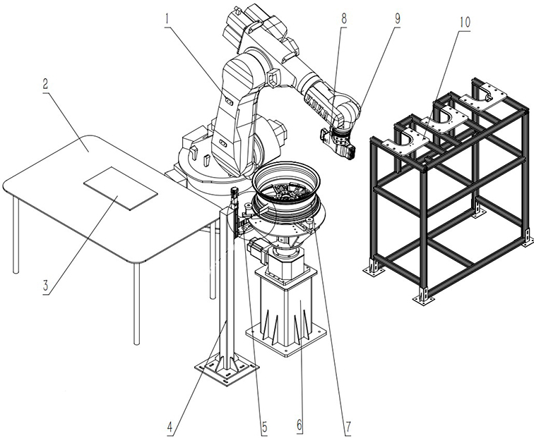
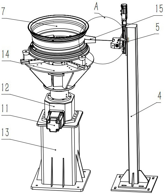
[0074] like figure 2 As shown, when the workpiece to be corrected is the hub to be corrected, the measuring mechanism includes a clamping and rotating device 6, a second line laser 5 and a measurement control module (not shown in the figure), wherein the clamping and rotating device is used to clamp the Calibrate the wheel hub and drive the wheel hub to be calibrated to rotate. The second line laser is used to measure the wheel hub to be calibrated. The measurement control module is connected with the clamping and rotating device and the second line laser, and is used to control the rotation of the clamping and rotating device and obtain according to the measurement. Calculate the difference between the hub to be calibrated and the reference hub based on the data, and obtain the machining allowance of the hub to be calibrated. During implementation, the wheel hub to be corrected is placed on the clamping and rotating device, and the measurement control module controls the rot...

Embodiment 3

[0080] combine Figure 2~Figure 4 As shown, when the workpiece to be corrected is the metal plate 3 to be processed and the hub 7 to be corrected, the measuring mechanism includes a first line laser (not shown in the figure), a second line laser 5, a clamping and rotating device, a measuring manipulator and A measurement control module, wherein the first line laser is connected to the measurement control module for measuring the metal sheet 3 to be processed, and the second line laser 5 is connected to the measurement control module for measurement of the wheel hub 7 to be corrected, clamping and rotating The device is connected to the measurement control module for clamping the wheel hub 7 to be calibrated and driving the wheel hub 7 to rotate. The measuring manipulator is connected to the first-line laser and the measurement control module for driving the first-line laser to move. The measurement control module It is used to control the measuring manipulator to control the f...


PUM


Abstract

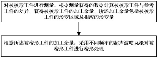
The invention discloses a workpiece shape correcting method and a workpiece shape correcting device. The workpiece shape correcting method comprises the steps that a to-be-corrected workpiece is measured, the difference between the to-be-corrected workpiece and a reference workpiece is calculated according to data obtained through measurement, the machining allowance of the to-be-corrected workpiece is obtained, and the machining allowance comprises a deformation area of the to-be-corrected workpiece and the corresponding deformation amount; according to the machining allowance of the to-be-shaped workpiece, ultrasonic shot blasting guns with different frequencies are adopted for conducting shape correction treatment on the to-be-shaped workpiece; and the steps are repeated until the corrected workpiece meets the correction standard. According to the device, a to-be-machined metal plate and a to-be-shaped hub can be subjected to shape correction treatment, the hub shape correction precision is improved, meanwhile, damage to the hub is avoided, and the application range is wide.

Description

technical field [0001] The invention belongs to the technical field of hub manufacturing, and in particular relates to a workpiece shape correction method and a workpiece shape correction device. Background technique [0002] The wheel hub is the metal part that supports the tire inside the tire. At present, the wheels on the market are mainly divided into two categories: steel wheels and alloy wheels. Small, strong heat dissipation and other advantages, more and more widely used. At present, most aluminum alloy wheels are cast with A356 material, but the mechanical properties of this material are relatively low. In order to improve the mechanical properties of the material, aluminum alloy wheels are usually heat-treated during the manufacturing process of the wheels. The yield strength will eventually cause the heat treatment deformation of the hub, which will cause roundness deformation (radial deformation) in the rim area, which will bring troubles to the subsequent mac...

Claims


Application Information

Patent Timeline
Patent Type & Authority Applications(China)
IPC IPC(8): B21D3/14B21D53/26B21C51/00B24C5/02
CPCB21C51/00B21D3/14B21D53/265B24C5/02
Inventor 陈思鲁肖涛李俊杰李荣赵夙仇斌权罗竞波翟锰钢张驰杨桂林
Owner NINGBO INST OF MATERIALS TECH & ENG CHINESE ACADEMY OF SCI
Learn More