Automatic assembling device and method for large-length-diameter-ratio shaft and hole

An automatic assembly device and a technology with a large aspect ratio, which is applied in metal processing, metal processing equipment, manufacturing tools, etc., can solve problems such as easy interference with the inner wall of the hole, damage to the shaft workpiece, etc.

Active Publication Date: 2021-06-29
INST OF MACHINERY MFG TECH CHINA ACAD OF ENG PHYSICS
View PDF15 Cites 3 Cited by
  • Summary
  • Abstract
  • Description
  • Claims
  • Application Information

AI Technical Summary

Problems solved by technology

[0006] The purpose of the present invention is to provide an automatic assembly device and method for a large length-to-diameter ratio shaft hole to solve the problem that the large long-diameter shaft is easy to interfere with the inner wall of the hole during assembly, thereby causing damage to the shaft workpiece

Method used


Image

  • Automatic assembling device and method for large-length-diameter-ratio shaft and hole

Examples


Embodiment 1

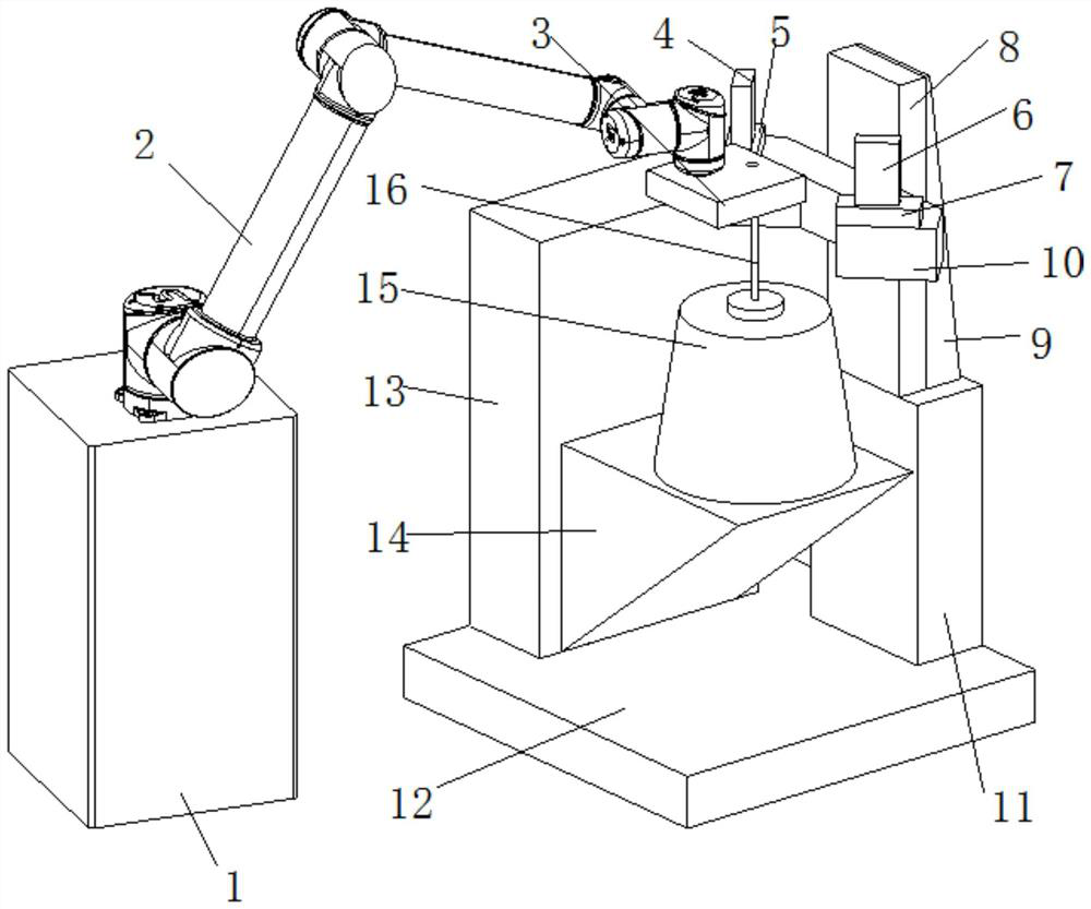
[0039] see figure 1 , a large aspect ratio shaft hole automatic assembly device, including:

[0040]A clamping unit, which includes: a workpiece with a hole 3 and a clamping member for clamping the workpiece with a hole 3, the clamping member can adjust the position and angle of the workpiece with a hole 3;

[0041] The attitude adjustment assembly unit includes: a shaft workpiece 16, a first lifting assembly, an attitude adjustment mechanism 15 for adjusting the position and angle of the shaft workpiece 16, and the first lifting assembly is used to control the lifting of the attitude adjustment mechanism 15, The shaft workpiece 16 is installed on the top surface of the attitude adjustment mechanism 15;

[0042] A measuring unit, which includes: a second lifting assembly and a measuring assembly, the second lifting assembly includes a second support plate 10, the second lifting assembly is used to control the lifting of the second support plate 10, the measuring assembly Ins...

Embodiment 2

[0058] The present invention also provides an automatic assembly method for a shaft hole with a large length-to-diameter ratio, which includes the following steps:

[0059] S1: Move the workpiece 3 with a hole through the clamping member to the area above the shaft workpiece 16, and adjust the laser line height of the first line laser profile sensor 6 and the second line laser profile sensor 4 to the height of the shaft workpiece 16 through the second lifting assembly At the top, record the position Z0 of the first lifting component at this time;

[0060] S2: Adjust the horizontal position of the first line laser profile sensor 6 and the second line laser profile sensor 4 through the first horizontal movement axis 7 and the second horizontal movement axis 5, so that the axis workpiece 16 is between the first line laser profile sensor 6 and the second line Within the measurement range of the laser profile sensor 4;

[0061] S3: Elevate the position of the shaft workpiece 16 at...


PUM


Abstract

The invention discloses an automatic assembling device and method for a large-length-diameter-ratio shaft and a hole, and relates to the technical field of assembling of workpieces of large-length-diameter-ratio shafts and holes. By adopting a clamping assembly capable of adjusting the position and angle of a workpiece with the hole, a posture adjusting mechanism capable of adjusting the position and posture of the shaft workpiece (shaft), and a first lifting assembly and a second lifting assembly which are capable of adjusting the vertical position of the posture adjusting mechanism and the testing position of a measuring assembly respectively, a posture vector Am of a local area of the shaft workpiece and a posture vector A1 of the hole can be measured, so that the shaft workpiece posture adjusting amount deltaAm which needs to be executed by the posture adjusting mechanism is acquired; and real-time adjustment can be conducted in the assembling process of the shaft workpiece and the workpiece with the hole, so that it is guaranteed that the shaft workpiece does not make contact with the inner wall of the hole of the workpiece with the hole, thus the situations of interference and shaft workpiece damage are avoided, and the assembling quality and efficiency are improved.

Description

technical field [0001] The invention relates to the technical field of workpiece assembly with large aspect ratio shaft holes, in particular to an automatic assembly device and method for large aspect ratio shaft holes. Background technique [0002] Shaft hole assembly is a common assembly method in the field of machinery manufacturing. With the development of the field of machinery manufacturing towards ultrasonic high-precision and high-quality manufacturing, the accuracy and quality requirements of shaft hole assembly continue to improve. [0003] For slender shafts with large aspect ratio (usually the ratio of length to diameter is greater than 100), due to the poor rigidity of the slender structure, the manufacturing and processing accuracy is usually low, and there are large radial deformation and deformation during the manufacturing and storage process. The problem of random directions brings great difficulties to the assembly of the shaft hole. During the assembly pr...

Claims


Application Information

Patent Timeline
Patent Type & Authority Applications(China)
IPC IPC(8): B23P19/12B23P19/10B23P19/04
CPCB23P19/12B23P19/105B23P19/04
Inventor 张连新孙鹏飞付磊宋颖慧张思煜李翔庞培川肖虹
Owner INST OF MACHINERY MFG TECH CHINA ACAD OF ENG PHYSICS
Why Eureka
Try Eureka