Floating pressing plate head with adjustable clamping force

A technology of floating platen and clamping force, which is applied in the direction of clamping, supporting, positioning devices, etc., can solve the problems of difficult control of clamping force, lower product quality, looseness, etc., and achieve reduced operation difficulty, continuous and effective clamping, and improved The effect of compression deformation

Pending Publication Date: 2021-06-29
田中金属加工(上海)有限公司
View PDF0 Cites 1 Cited by
  • Summary
  • Abstract
  • Description
  • Claims
  • Application Information

AI Technical Summary

Problems solved by technology

Each clamping method is only suitable for one type of product. For thin-walled parts with complex structure, the clamping method of pressing plate is mainly used. Due to the complex structure of the product, it is inconvenient to use auxiliary support, which is expensive and inefficient. ; Without auxiliary support, it is easy to clamp deformation or clamp loose
When the clamping force is too large, the product will be severely deformed by the force, which will affect the product quality and cause the product to be scrapped
When the clamping force is too small, the product will move during processing, resulting in product scrap or even tool damage
Therefore, the magnitude of the clamping force is very difficult to control, and during the processing of the product, after cutting off part of the material, due to internal stress and product deformation, the support strength of the product becomes lower and deformation occurs at the same time, which easily causes the product to lose clamping force, greatly increasing the risk of product scrap and tool damage
At present, a large clamping force is mostly used to prevent such clamping failure, and at the same time, due to excessive clamping force, the scrap rate of industrial products is increased and the quality of the product is reduced.

Method used


Image

  • Floating pressing plate head with adjustable clamping force
  • Floating pressing plate head with adjustable clamping force
  • Floating pressing plate head with adjustable clamping force

Examples


Embodiment 1

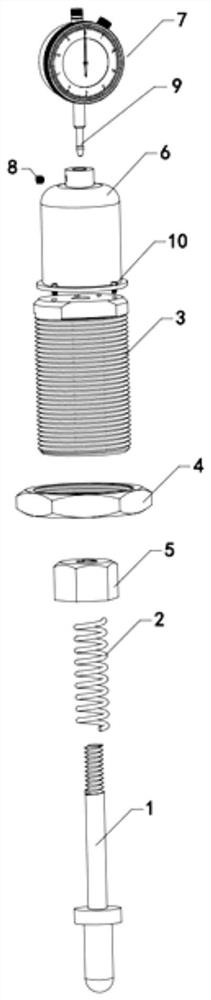
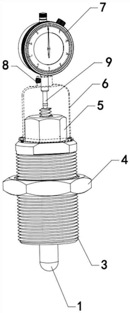
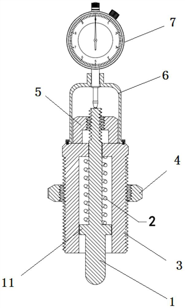
[0028] A floating platen head with adjustable clamping force, its structure see Figure 1-3 As shown, it includes a connecting body 3 that can be fixedly connected with the external pressure plate and specifically penetrates up and down through the hollow cavity, and the two ends respectively protrude from the upper and lower ends of the hollow cavity. The elastic part at the top of the cavity, the pre-adjustment part fixedly connected to the top of the movable pressure head 1 and against the top of the coupling body 3, and the pressure gauge 7 fixed above the coupling body 3, the probe 9 of the pressure gauge 7 is also against the movable The top of the indenter 1.

[0029] see you again Figure 1-Figure 3 As shown, the top of the coupling body 3 is also fixedly provided with a casing 6 covering the top of the presetter and the movable pressure head 1 , and a pressure gauge 7 is installed on the casing 6 . In this embodiment, the pressure gauge 7 is preferably fixed on the ...


PUM


Abstract

The invention relates to a floating pressing plate head with adjustable clamping force. The floating pressing plate head with the adjustable clamping force comprises a connector, a movable pressing head, an elastic piece, a pre-adjusting piece and a pressure gauge, wherein the connector can be fixedly connected with an external pressing plate and is provided with a vertically-through hollow cavity, the two ends of the movable pressing head extend out of the upper end and the lower end of the hollow cavity correspondingly, the two ends of the elastic piece abut against the movable pressing head and the top end of the hollow cavity correspondingly, the pre-adjusting piece is fixedly connected with the top of the movable pressing head and abuts against the top of the connector, the pressure gauge is fixed above the connector, and a probe of the pressure gauge further abuts against the top end of the movable pressing head. Compared with the prior art, the floating pressing plate head with the adjustable clamping force has the advantages that fixing of a traditional pressing plate head is changed into floating adjustment, different types of floating heads can be selected according to the pressing force range, and the situation of pressing deformation is greatly improved.

Description

technical field [0001] The invention belongs to the technical field of numerical control machining key parts and relates to a floating platen head with adjustable clamping force. Background technique [0002] At present, the clamping before product processing and testing mainly includes flat product clamping, vacuum suction cup clamping, pressure plate clamping, chuck clamping and side pressure clamping, etc. Each clamping method is only suitable for one type of product. For thin-walled parts with complex structure, the clamping method of pressing plate is mainly used. Due to the complex structure of the product, it is inconvenient to use auxiliary support, which is expensive and inefficient. ; Without auxiliary support, it is easy to clamp deformation or clamp loose. When the clamping force is too large, the product will be severely deformed by the force, which will affect the product quality and cause the product to be scrapped. When the clamping force is too small, the ...

Claims


Application Information

Patent Timeline
Patent Type & Authority Applications(China)
IPC IPC(8): B23Q3/06B23Q17/00
CPCB23Q3/06B23Q17/005
Inventor 秦国军王招生卢贵慧王斌
Owner 田中金属加工(上海)有限公司
Why Eureka
Try Eureka